EasyManuals Logo

LSIS SV-IS7 User Manual

LSIS SV-IS7
255 pages
To Next Page IconTo Next Page
To Previous Page IconTo Previous Page
Page #123 background imageLoading...
Page #123 background image
112
6.1.3.1
Setting a Frequency Reference for 010 V Input
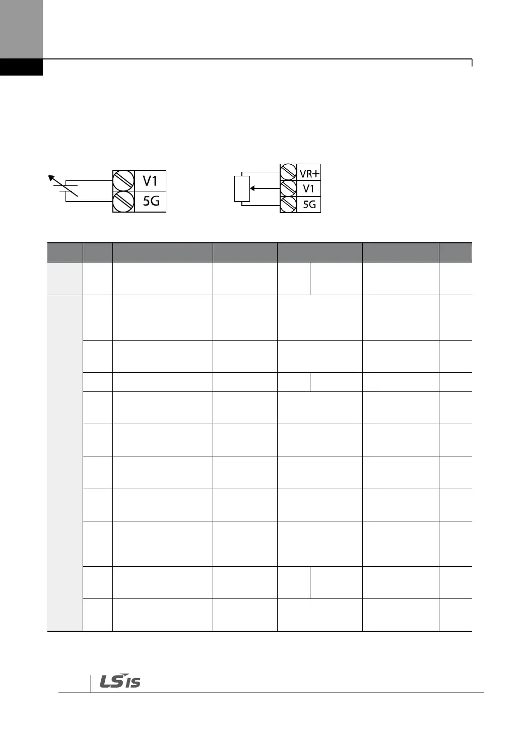
Set IN-06 (V1 Polarity) to “0 (unipolar)”. Use a voltage output from an external source or use the
voltage output from the VR terminal to provide inputs to V1. Refer to the diagrams below for
the wiring required for each application.
[External source application] [Internal source (VR) application]
Group
Code
Name
LCD Display
Parameter Setting
Setting Range
Unit
DRV
07
Frequency reference
source
Freq Ref Src
2
V1
09
-
IN
01
Frequency at
maximum analog
input
Freq at 100%
Maximum
frequency
0.00
max. frequency
Hz
05
V1 input monitor
V1
Monitor[V]
0.00
0.0010.00
V
06
V1 polarity options
V1 Polarity
0
Unipolar
01
-
07
V1 input filter time
constant
V1 Filter
10
010000
ms
08
V1 minimum input
voltage
V1 volt x1
0.00
0.0010.00
V
09
V1 output at
minimum voltage (%)
V1 Perc y1
0.00
0.00100.00
%
10
V1 maximum input
voltage
V1 Volt x2
10.00
0 .00 10.00
V
11
V1 output at
maximum voltage
(%)
V1 Perc y2
100.00
0100
%
16
Rotation direction
options
V1 Inverting
0
No
01
-
17
V1 quantizing level
V1
Quantizing
0.04
0.00*, 0.04
10.00
%
* Quantizing is disabled if0” is selected.

Table of Contents

Questions and Answers:

Question and Answer IconNeed help?

Do you have a question about the LSIS SV-IS7 and is the answer not in the manual?

LSIS SV-IS7 Specifications

General IconGeneral
BrandLSIS
ModelSV-IS7
CategoryInverter
LanguageEnglish

Related product manuals