0–10 V Input Voltage Setting Details
Configures the frequency reference at the maximum input voltage when a
potentiometer is connected to the control terminal block. A frequency set with
code IN-01 becomes the maximum frequency only if the value set in code IN-
11 (or IN-15) is 100%.
• Set code IN-01 to 40.00 and use default values for codes IN-02–IN-16. The
motor will run at 40.00 Hz when a 10 V input is provided at V1.
• Set code IN-11 to 50.00 and use default values for codes IN-01–IN-16. The
motor will run at 30.00 Hz (50% of the default maximum frequency–60
Hz) when a 10 V input is provided at V1.
Configures the inverter to monitor the input voltage at V1.
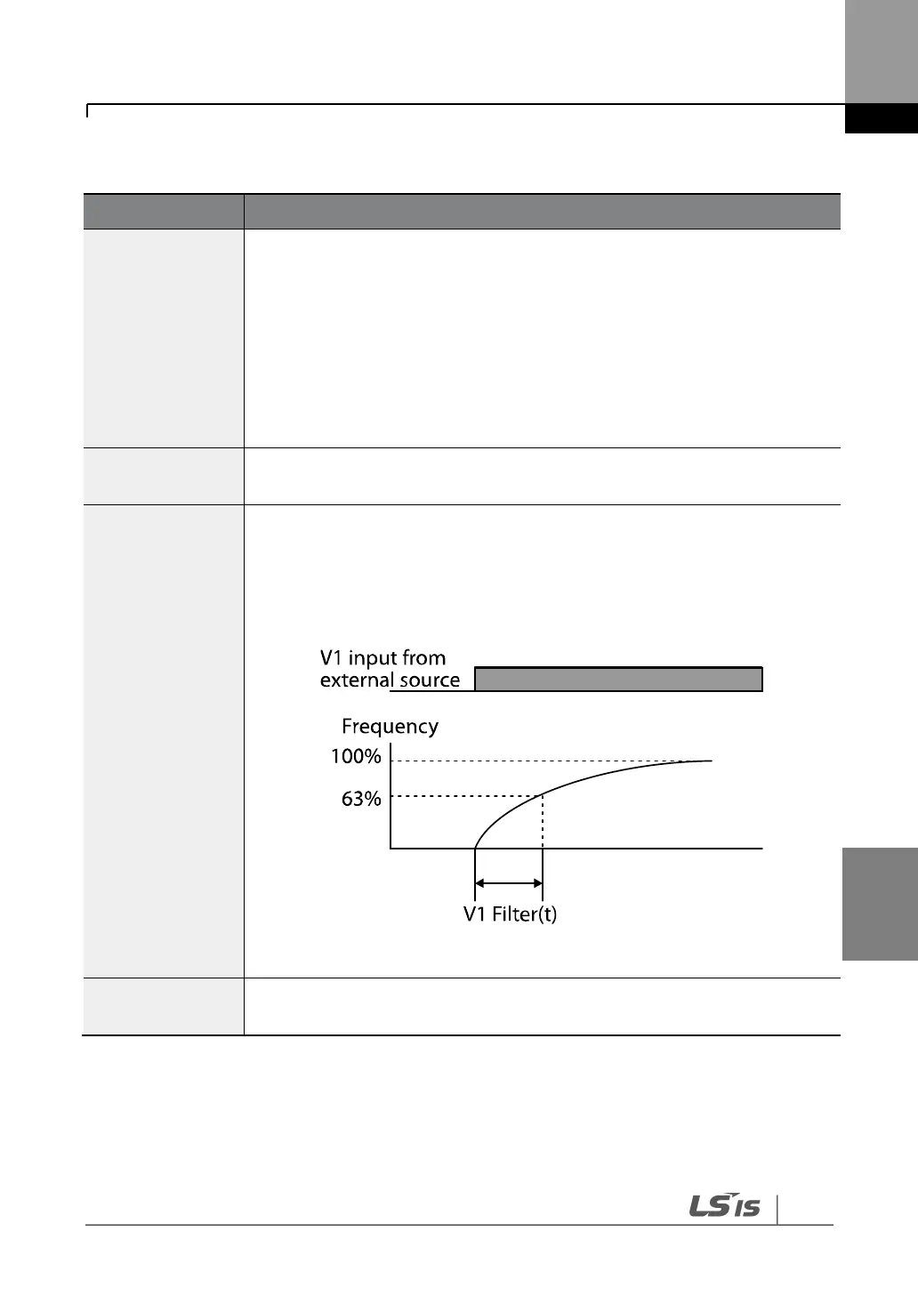
The V1 filter may be used when there are large variations between reference
frequencies. Variations can be mitigated by increasing the time constant, but
this requires an increased response time.
The value t (time) indicates the time required for the frequency to reach 63%
of the reference, when external input voltages are provided in multiple steps.
[V1 Filter ]
IN-08 V1 volt x1–
IN-11 V1 Perc y2
These parameters are used to configure the gradient level and offset values of
the output frequency, based on the input voltage.

 Loading...


