Page 198
REPAIR INSTRUCTIONS, PART 1
REMOVAL
Camshaft bushings are identified in sequence,
1 to 7, starting from the front of the engine.
1. Using camshaft bushing remover/installer
J 42377 (with J 21428-01 Cam Bushing
Installer Set) and a hammer, remove the
No. 1 camshaft bushing from the cylinder
block. Refer to Figure 199.
199
Figure 199 — Camshaft Bushing Removal
2. Remove the remaining six bushings in
sequence.
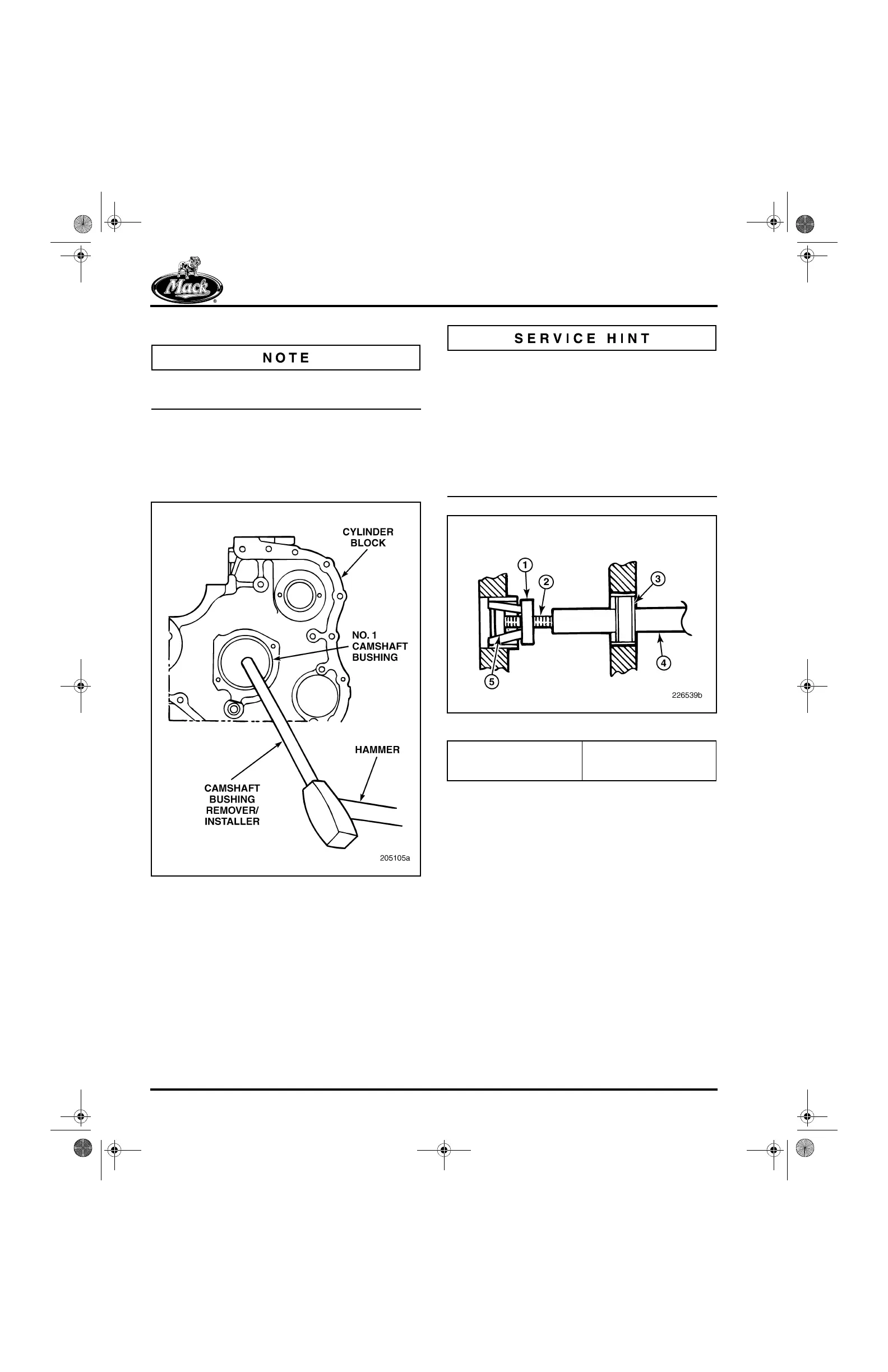
If the camshaft bushings are being replaced in
the chassis, a special tool is required to remove
the No. 7 camshaft bushing. The tool is included
with the J 21428-01 kit. The No. 7 cam bushing
removal tool consists of a bushing puller
(J 21385-1), a cone (J 21385-4), a threaded
mandrel (J 21248-4) and a guide (J 21428-4).
These parts are threaded onto the handle
(J 21099-9), and a slide hammer is then used to
remove the bushing.
200
Figure 200 — Rear Cam Bushing Removal Tool
3. Check the bushing bore diameters and finish
in the cylinder block, using a telescoping
gauge or inside micrometer.
1. Bushing Puller
(J 21385-1)
2. Mandrel (J 21248-4)
3. Guide (J 21428-4)
4. Handle (J 21099-9)
5. Cone (J 21385-4)
5-111.bk Page 198 Monday, July 10, 2006 2:26 PM