REPAIR INSTRUCTIONS, PART 1
Page 199
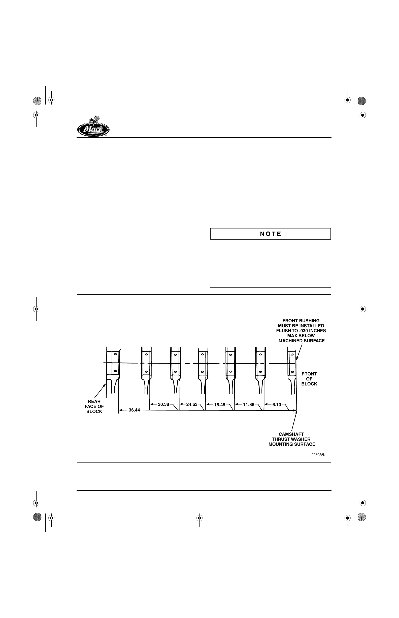
CAMSHAFT BUSHING ALIGNMENT
Each camshaft bushing is located at set
distances from the camshaft thrust washer
mounting surface to the forward edge of the
bushing. Refer to Figure 201.
When installed to the proper dimensions, the
intermediate bushings (locations 2, 3, 5 and 6)
are approximately centered in their bores, in the
front-to-rear direction. The front, center and rear
bushings, however, are not centered. The offsets
are described as follows:
앫 No. 1 bushing — Installed with the front of
the bushing flush, to 0.030 inch (0.762 mm)
behind the front face of the bore. There is
approximately 1/8 inch (3.18 mm) of the
bore visible on the rear side of the bushing.
앫 No. 4 bushing — When installed correctly,
there is approximately 0.400 inch (10 mm) of
bore visible at the front face of the bushing,
and approximately 0.040 inch (1 mm) of
bushing protrusion from the rear of the bore.
앫 No. 7 bushing — When installed correctly,
there is an approximate 1/8-inch (3.18 mm)
wide section of bore visible at the front face
of the bushing.
Installing the cam bushings to the correct
dimensions optimizes bushing-to-cylinder block
oil hole alignment. Even when installed to the
proper dimensions, however, the No. 1 and No. 4
bushings have only approximately 1/2 to 2/3 of
the oil hole in alignment with the oil hole in the
bore; 100 percent oil hole alignment is not
attainable or required.
Camshaft bushings (part No. 57GB37) have a
groove, 360 degrees around the inside diameter.
The grooved bushings can be used with either
grooved or non-grooved camshaft journals, and
the camshaft with grooved journals can be used
with either grooved or non-grooved bushings.
Parts can be intermixed in an engine.
201
Figure 201 — Camshaft Bushing Locations
5-111.bk Page 199 Monday, July 10, 2006 2:26 PM