REPAIR INSTRUCTIONS, PART 1
Page 203
206
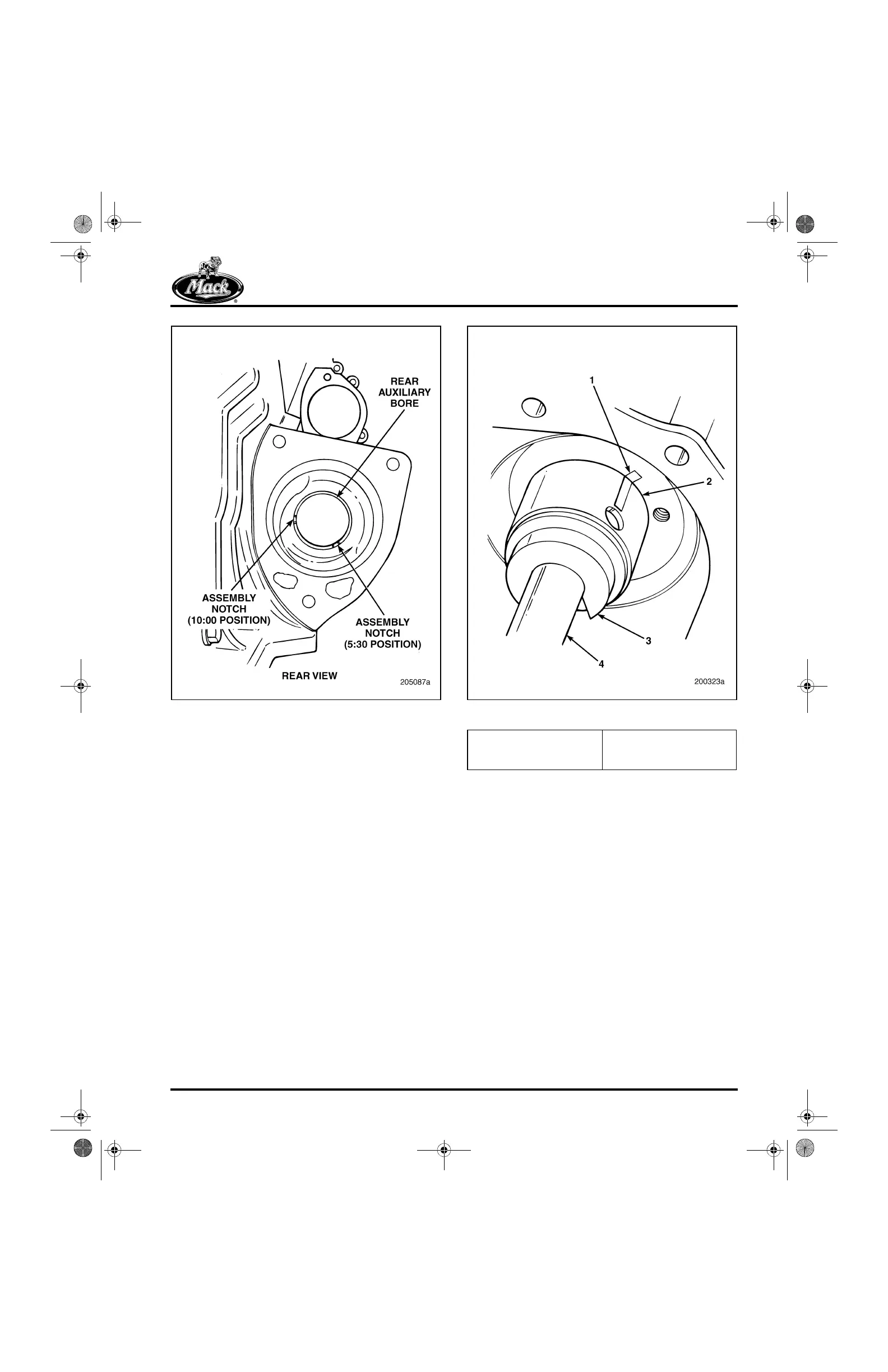
Figure 206 — Rear Auxiliary Bushing Alignment
1. Clean the surfaces of the bushing and the
bore. Dry both surfaces with compressed
air.
2. Using a dark-colored felt-tip marker, mark
the cylinder block and the bushing with a line
to facilitate correct alignment during
installation. Refer to Figure 207.
3. Position the replacement bushing against
the front face of the block at the front
bushing bore. Align the oil hole in the
bushing with the hole in the block.
207
Figure 207 — Auxiliary Shaft Bushing Alignment
4. Using camshaft bushing removal/installation
tool J 21428-01 and the appropriate pilot
adapter J 21428-12, install the bushing.
5. Check the bushing surface for burrs caused
by installation.
6. After the bushing is in place, measure the ID
to ensure that the bushing is not undersize
because of burrs on the OD caused by
installation. Refer to the “Fits and Limits”
chart in the SPECIFICATIONS section for
the bushing ID dimensions.
7. Working from the front of the cylinder block,
repeat steps 1 through 6 to install the front
bushing.
8. Bushings must be installed to the depths
described in Figure 208.
1. Alignment Mark
2. Bushing
3. Pilot Adapter J 21428-12
4. Camshaft Bushing
Remover/Installer
(J 21428-01 Kit)
5-111.bk Page 203 Monday, July 10, 2006 2:26 PM