Page 222
REPAIR INSTRUCTIONS, PART 1
4. Set the camshaft close to the oven in which
the camshaft gear will be heated. It should
be set vertically on the floor with the front of
the shaft up. Secure the shaft so it cannot
wobble or fall over as the gear is being
installed.
5. Heat the camshaft gear to 425°F (204°C) in
an oven (preferred — an old kitchen oven is
sufficient) or on an industrial grade hot plate
used in combination with the
temperature-sensing equipment described
earlier. Adequate heating will require one to
two hours. DO NOT heat the gear for more
than two hours nor exceed 425°F (204°C) as
heat treatment may be affected.
DO NOT attempt to heat the gear with a torch.
This method will only provide localized heating,
will not permit proper expansion and may affect
heat treatment of the gear.
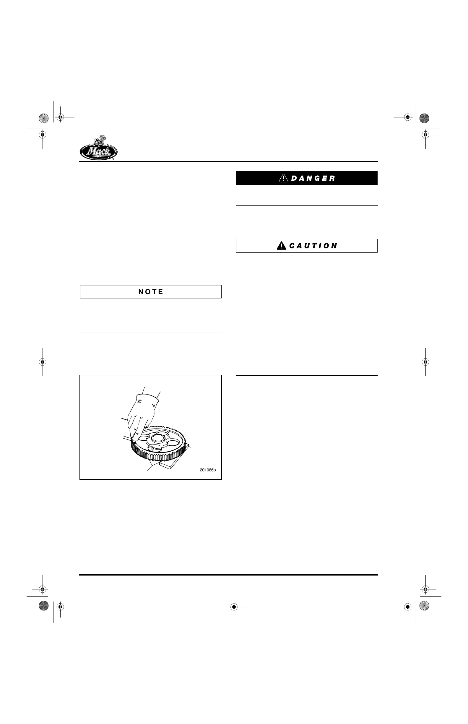
6. Remove the gear from the oven and position
it on the camshaft with the keyway and key
aligned and the timing marks facing up
(Figure 229).
229
Figure 229 — Camshaft Gear Installation, Heat Method
Wear protective gloves when handling the
heated gear.
7. Using a quick, steady motion, push
downward on the gear until the gear is fully
seated against the cam shoulder surface.
The heat-expanded gear bore will begin to
transfer heat to the camshaft as soon as contact
between the gear and shaft is made. Therefore, it
is absolutely necessary that the gear be installed
in one rapid motion to the fully seated position.
If the gear is allowed to stop on the camshaft
before it is fully seated, it will become immovable.
If this occurs, DO NOT press the gear onto the
camshaft. Instead, remove the gear with a press
and thoroughly inspect the gear bore, camshaft
journal and key. If there is no scoring, galling or
tearing, repeat the installation procedure using
the removed components. If damage is minimal,
repair the components and reinstall. If the
damage is significant, the components must be
replaced.
8. Allow the gear to cool.
9. When the gear is fully seated, there should
be 0.003–0.012 inch (0.076–0.31 mm)
clearance between the rear face of the gear
and the thrust washer. This clearance can
be measured with a feeler gauge.
5-111.bk Page 222 Monday, July 10, 2006 2:26 PM