REPAIR INSTRUCTIONS, PART 1
Page 225
4. Apply a suitable lubricant to the bushing and
broach. Then, press the broach through the
bushing to expand the bushing for a tight fit
in the wrist pin bore.
Refer to Figure 233.
Make certain that the bushing is fully expanded
for a tight fit in the connecting rod bore or it will
loosen, rotate and fail.
Use care not to twist or bend the connecting rod
while pressing the broach through the bushing.
5. Clean all shavings from the rifle-drilled hole
in the rod.
6. Check the alignment of the connecting rod in
the following procedure for twist or bend.
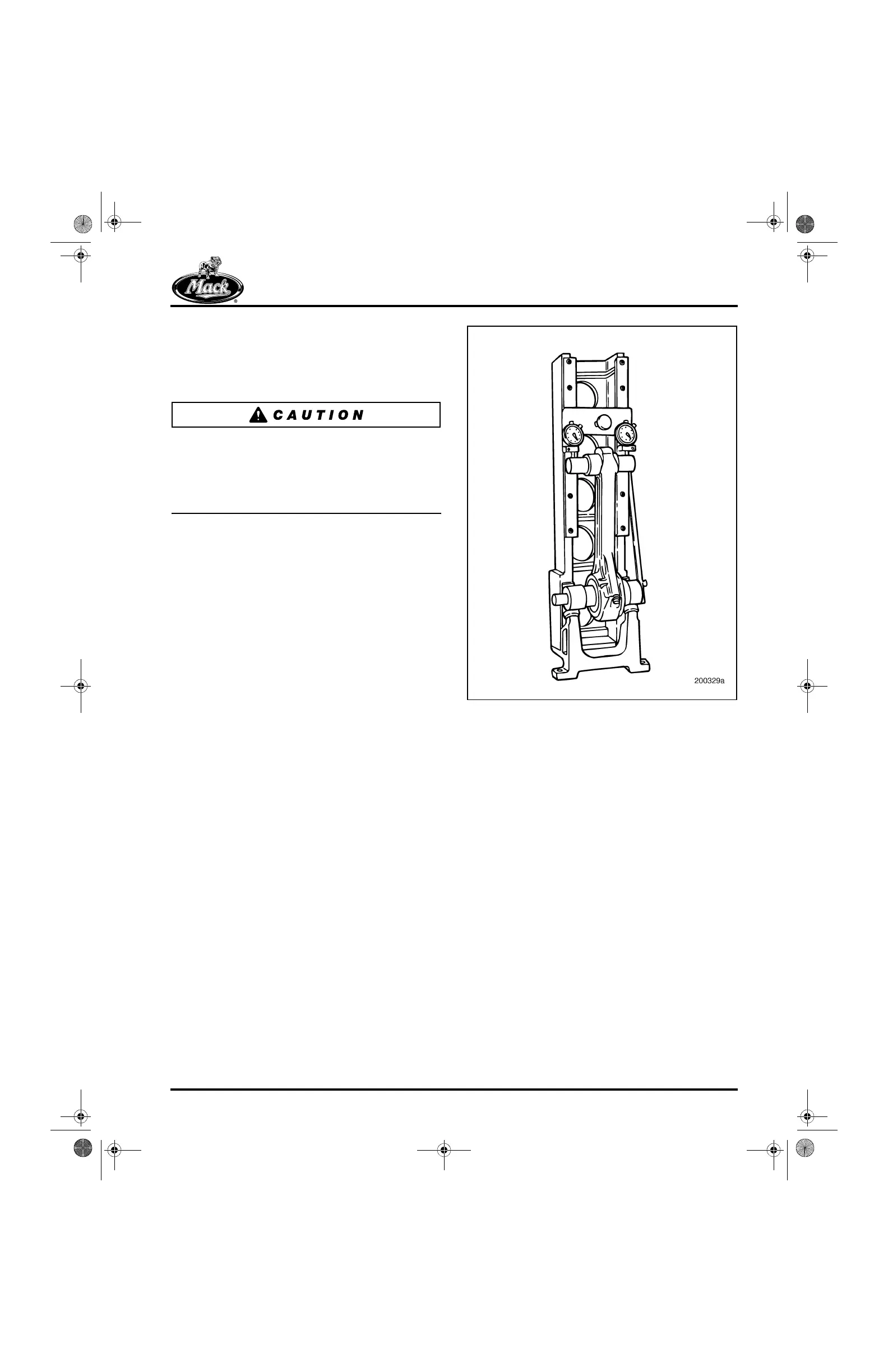
CONNECTING ROD ALIGNMENT CHECK
1. Position the connecting rod in a connecting
rod fixture, Sweeney 945-6041, or
equivalent. Use the appropriate mandrel and
plunger extension applicable for the engine.
233
Figure 233 — Connecting Rod Fixture
2. Check the rod for twist or bend exceeding
the following specifications. Specified
distances are center-to-center.
앫 Maximum twist of the connecting rod
within 12 inches (30.5 cm) is 0.010 inch
(0.254 mm).
앫 Maximum bend of the connecting rod
within 12 inches (30.5 cm) is 0.004 inch
(0.102 mm).
5-111.bk Page 225 Monday, July 10, 2006 2:26 PM