REPAIR INSTRUCTIONS, PART 1
Page 231
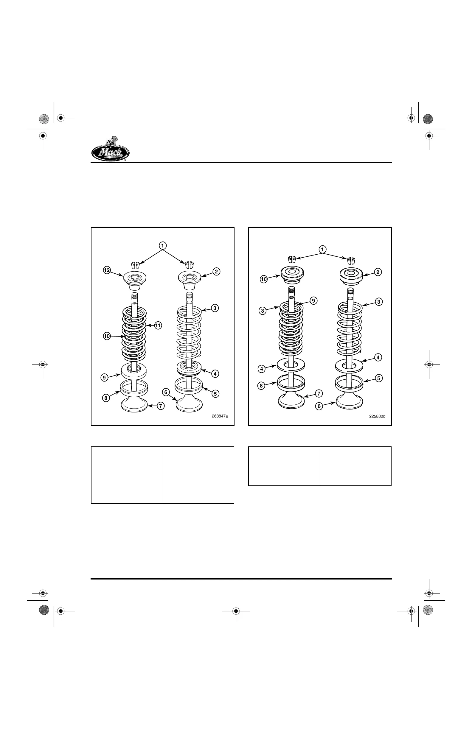
Bottom Rotators
The current configuration of the ASET™ engine
uses a bottom valve rotator installed under the
valve springs. Removal of the bottom inlet and
the exhaust valve rotators requires the use of tool
J 29294-B.
242
Figure 242 — Valve Spring, Rotator and Valve Seats
(Current Design — Mid-2003 and Later)
Tip-End Rotators
ASET™ engines used a tip-end valve rotator
installed at the top of the valve springs until
approximately mid 2003 (Figure 243). Removal of
the “tip-end” inlet and the exhaust valve rotators
requires the use of tool J 43887.
243
Figure 243 — Valve Spring, Rotator and Valve Seats
(Non-Current Design — Prior to Mid-2003)
The inlet and exhaust valve rotators are different.
The rotators installed on the exhaust valves are
stepped to accommodate the dual-spring
arrangement used at the exhaust locations. The
exhaust rotator contains a second level which
supports the inner spring used on exhaust valves;
the inlet rotator contains only a single level. This
difference is shown in Figure 244.
1. Valve Spring Washer
Keys
2. Valve Retaining Washer,
Inlet
3. Single Valve Spring
4. Bottom Valve Rotator,
Inlet
5. Valve Seat, Inlet
6. Inlet Valve
7. Valve, Exhaust
8. Valve Seat, Exhaust
9. Bottom Valve Rotator,
Exhaust
10. Valve Spring, Inner
11. Valve Spring, Outer
12. Valve Retaining
Washer, Outer
1. Valve Spring Rotator
Keys
2. Tip-End Rotator, Inlet
3. Valve Spring
4. Spring Seat
5. Valve Seat, Inlet
6. Valve, Inlet
7. Valve, Exhaust
8. Valve Seat, Exhaust
9. Valve Spring, Inner
10. Tip-End Rotator,
Exhaust
5-111.bk Page 231 Monday, July 10, 2006 2:26 PM