Page 232
REPAIR INSTRUCTIONS, PART 1
244
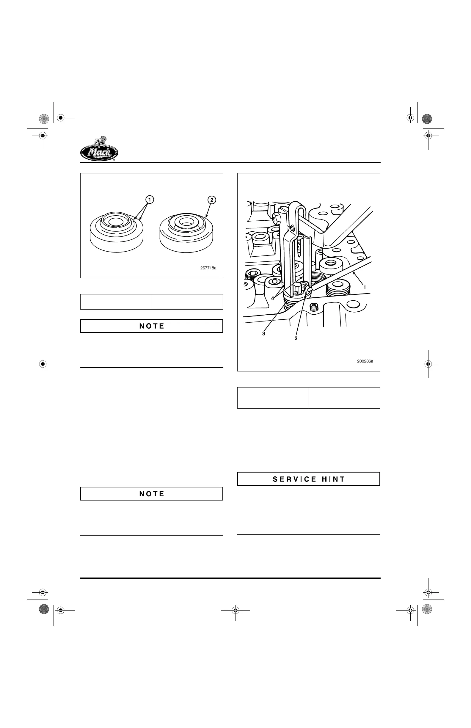
Figure 244 — Valve Rotators
Do not clean the tip-end rotators in a hot tank or
use any type of cleaning method which could
introduce contaminants to the rotator’s internal
parts or damage the rotator insert.
REMOVAL PROCEDURE
Refer to Figure 245.
1. Attach the valve spring compressor to the
cylinder head. Use compressor J 43887 for
valves with tip-end rotators or J 29294-B for
valves with bottom rotators.
2. Rest the tool compression forks on top of the
tip-end rotator or valve retaining washer and
center the forks above the valve.
3. Depress the tool handle until the valve
spring is compressed. Remove the valve
keys using a magnet.
Valve spring compressor J 43887 or J 29294-B
must be repositioned for each series of valves
(two inlet and two exhaust per cylinder). Drilled
and tapped holes are provided for each cylinder.
245
Figure 245 — Valve Spring Keeper Removal
4. For engines built with bottom rotators,
following valve spring key (keeper) removal,
remove valve retaining washers followed by
the single springs on the inlet valves and the
inner and outer springs on the exhaust
valves. After the springs are removed,
remove the bottom rotators and valves.
Current-production exhaust location inner springs
are now being painted white. These springs are
completely interchangeable with the former bare
steel springs. The white paint was added to help
verify that the inner spring is present after the
cylinder head is built-up.
1. Exhaust Rotator Spring
Support Area
2. Inlet Rotator Spring
Support Area
1. Magnet
2. Valve Spring Keys
(Keepers)
3. Tip-End Rotator or Valve
Retaining Washer
4. Tool Compression Forks
5-111.bk Page 232 Monday, July 10, 2006 2:26 PM