Page 274
REPAIR INSTRUCTIONS, PART 1
앫 Standard E-Tech™/ASET™ with Oil
Pressure Relief Valve Spacers
This oil pump configuration is very similar to
the original oil pump configuration except
that two spacers have been added to the
relief valve cap. These spacers are used to
provide a 15 psi reduction to cold oil
pressure, with no change to hot oil pressure.
These spacers were factory installed on MR
and LE chassis oil pumps only since
January 2003 and have been field installed
on many other oil pumps per Service Bulletin
SB-219-013 instructions.
304
Figure 304 — Oil Pump Pressure Relief Valve Spacers
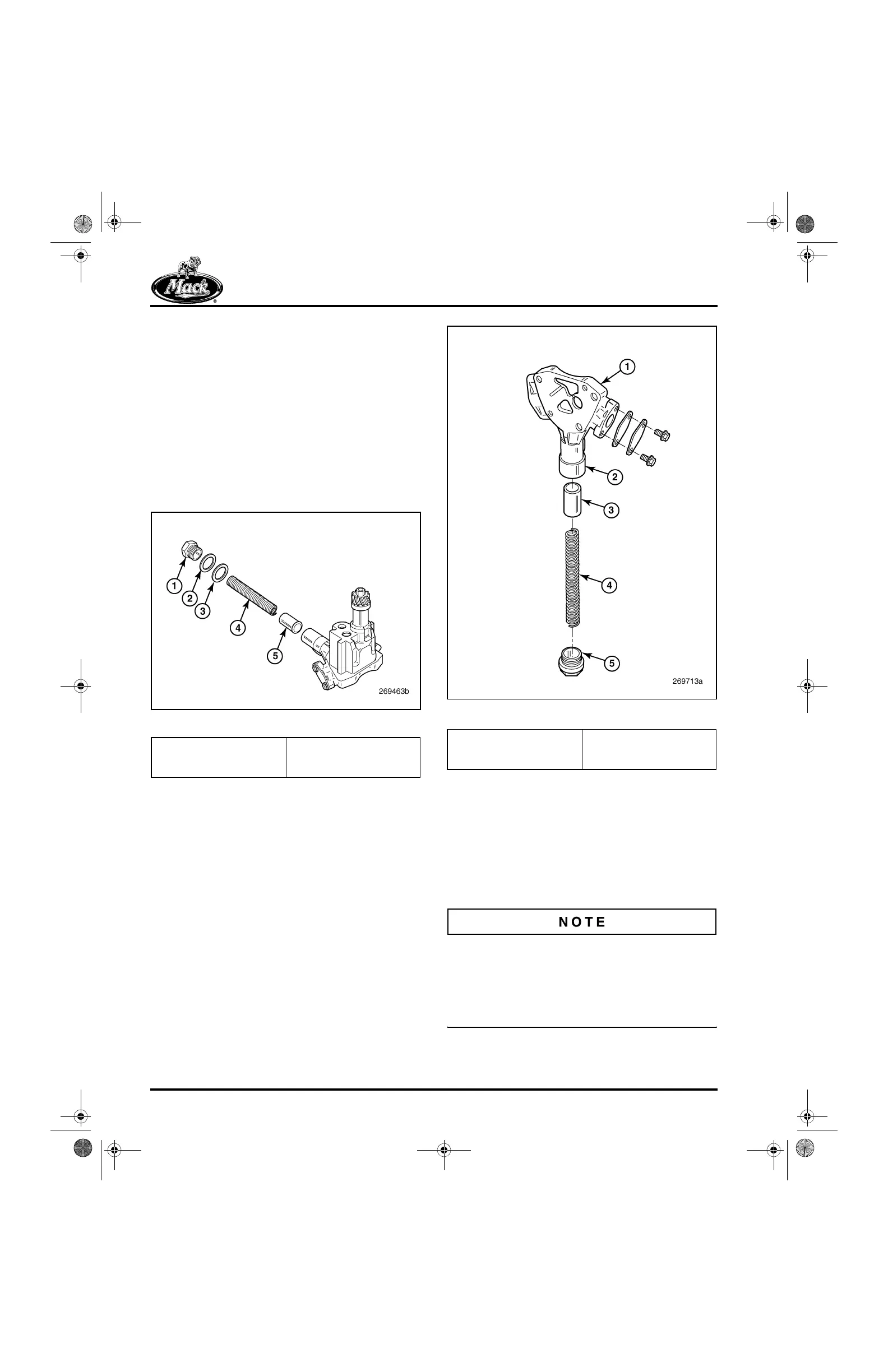
앫 ASET™ with Redesigned Oil Pressure
Relief Valve Cap
New production oil pumps introduced in
mid-2004 have a larger relief valve cap in
which the spring pocket is counterbored to
provide a 15 psi reduction to cold oil
pressure. No washers are needed or to be
installed on the larger relief valve cap.
305
Figure 305 — Oil Pump Pressure Relief Valve
DISASSEMBLY
Refer to Figure 306.
1. For ease of disassembly, reinstall the oil
pump in the cylinder block or in a suitable
holding fixture.
2. Remove the oil inlet (pickup) tube and
screen assembly (not shown).
Before inlet tube removal, note the orientation of
the tube for reassembly purposes. Inlet tubes are
positioned differently for front and rear sump
applications. Caution must be used to ensure that
the correct mounting holes are used for the
proper sump application.
1. Cap
2. Spacer, 0.093″ Thick
3. Spacer, 0.125″ Thick
4. Spring
5. Plunger
1. Oil Pump Housing Cover
2. Relief Valve Housing
(Larger Bore)
3. Plunger
4. Relief Valve Spring
5. Relief Valve Cap (Larger)
5-111.bk Page 274 Monday, July 10, 2006 2:26 PM