REPAIR INSTRUCTIONS, PART 1
Page 277
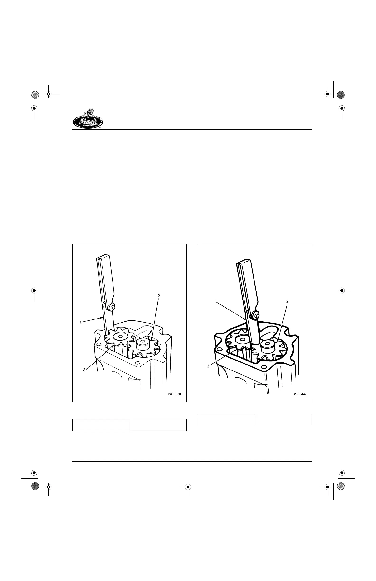
Side Clearance Check
Refer to Figure 308. With the straightedge
positioned across the housing and the face of the
gears, check side clearance as follows:
앫 Low Limit — Insert a 0.002-inch (0.051 mm)
thickness gauge between side of the gears
and the housing. The gauge should pass
between the gears and housing without
drag. If it drags, check the housing and
gears for nicks or burrs. Replace as
necessary.
앫 High Limit — Insert a 0.006-inch (0.152 mm)
thickness gauge between the gears and
housing. The gauge should not pass
through. If the gauge passes through,
replace the housing.
308
Figure 308 — Oil Pump Gear/Idler Gear Assembly Side
Clearance Check
Backlash Check
Refer to Figure 309.
Check the backlash between the pump gear and
idler gear with a thickness gauge.
앫 Low Limit — Insert a 0.013-inch (0.33 mm)
thickness gauge between the pump idler
gear and pump gear. The gauge should
pass between the gears without binding. If
binding occurs, check for nicks or burrs.
Replace as necessary.
앫 High Limit — Insert a 0.028-inch (0.711 mm)
thickness gauge between the pump idler
gear and pump gear. The gauge should not
pass through. If the gauge passes through,
replace the gears.
309
Figure 309 — Checking Oil Pump Gear Backlash
1. Thickness Gauge
2. Pump Idler Gear
3. Pump Gear
1. Thickness Gauge
2. Pump Idler Gear
3. Pump Gear
5-111.bk Page 277 Monday, July 10, 2006 2:26 PM