Page 276
REPAIR INSTRUCTIONS, PART 1
INSPECTION AND CLEARANCE CHECKS
Refer to Figure 306.
1. Clean and inspect the oil pump housing for
scoring, cracks or other damage. If any of
these conditions exist, replace the oil pump.
2. Check the bushings in the pump housing for
burrs, nicks or cracks.
The bushings are an integral part of the oil pump
housing. If the bushings are damaged, replace
the oil pump housing.
3. Clean and inspect the relief valve spring for
breaks. Replace as necessary.
4. Clean and inspect the plunger outer
diameter for galling and scoring. Light
galling or scoring will not affect function of
the plunger; if moderate-to-heavy, replace
both the plunger and cover.
5. Inspect the plunger seating surface for burrs
or nicks. If the seating surface contains burrs
or nicks, repair the seat as follows:
a. Place valve lapping compound on the
plunger seat.
b. Insert the plunger in the relief valve
housing and rotate the plunger against
the seat to smooth the seat.
c. Remove the plunger and clean it.
6. Check the pump idler gear for free play by
spinning it on its shaft. If any binding occurs,
check the housing bore and gear teeth for
burrs, nicks or other damage. Replace as
necessary.
7. Insert the integral pump gear and shaft, and
thrust washer into the housing; check for
free play by spinning the gear. If any binding
occurs, check the housing and gear teeth for
burrs, nicks or other damage. Replace as
necessary.
Before proceeding with assembly of the pump,
insert the integral pump gear and shaft, and idler
gear in the housing. Check end clearance, side
clearance and backlash of the gears as follows.
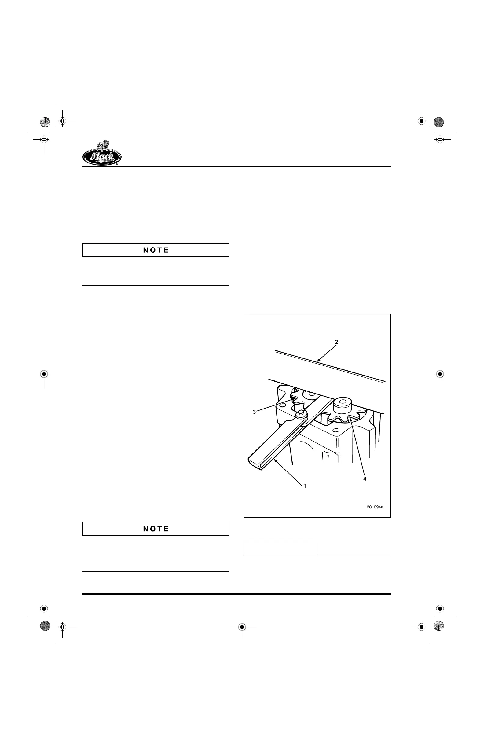
End Clearance Check
Refer to Figure 307. With the pump gear and idler
gear in place, position a straightedge across the
housing and the face of the gears. Check end
clearance as follows:
앫 Low Limit — Run a 0.003-inch (0.076 mm)
thickness gauge between the straightedge
and the gears. The gauge should move
freely without binding. If binding occurs,
check the gears for nicks or burrs. Replace
as necessary.
앫 High Limit — Run a 0.007-inch (0.178 mm)
thickness gauge between the straightedge
and the gears. The gauge should be very
tight. If the gauge moves freely, replace the
gears.
307
Figure 307 — Oil Pump Gear/Idler Gear Assembly End
Clearance Check
1. Thickness Gauge
2. Straightedge
3. Pump Gear
4. Pump Idler Gear
5-111.bk Page 276 Monday, July 10, 2006 2:26 PM