REPAIR INSTRUCTIONS, PART 1
Page 297
The angle-torque method applies for 14 mm
capscrew part Nos. 396GC211M and
396GC212M with partial and full threaded
shanks, respectively. Intermixing the partial and
full threaded 14 mm capscrews on the same
connecting rod is permissible.
4. Remove the capscrews and cap.
5. Check the width of the Plastigage on the
removed cap using a Plastigage width chart.
After measuring the width, remove the
Plastigage from the bearing.
6. If the clearance is not within specification,
correct the clearance as required:
앫 If the clearance is less than specified,
check behind the bearing for dirt, chips
or burrs which would prevent the
bearing from seating properly.
앫 If the bearing bores and inserts are
clean and undamaged, replace the
inserts with inserts sized to provide the
specified clearance.
7. Reposition the cap on the journal. Lubricate
the capscrews with clean engine oil, install
the capscrews and tighten to the specified
torque, 30 lb-ft (41 N폷m) plus 90 degrees
using torque angle gauge set BT 91104, or
equivalent.
If the cap and rod are not properly aligned,
bearing and rod damage may result.
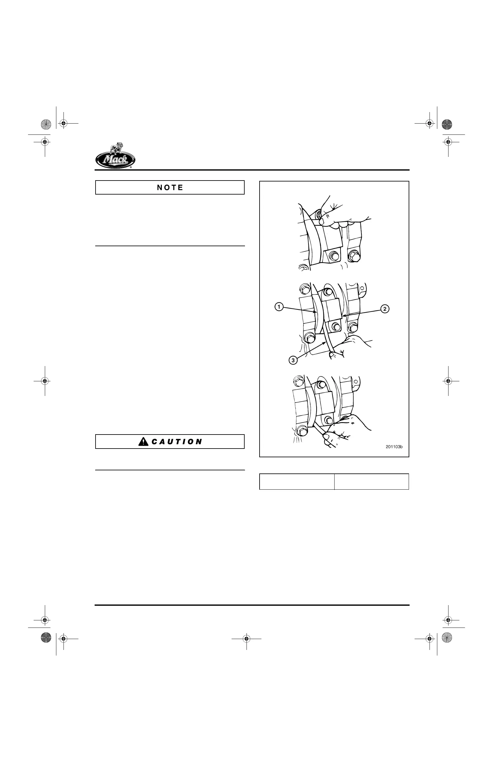
8. Check the rod side clearance (Figure 334)
by installing a thickness gauge between the
rod and the side of the journal. Check along
the entire parting line area.
334
Figure 334 — Connecting Rod Side Clearance Check
9. The clearance must be within the
specification listed under “Fits and Limits” in
the SPECIFICATIONS section. If not,
recheck for proper cap and rod alignment.
1. Crankshaft Journal
2. Rod Bearing Cap
3. Thickness Gauge
5-111.bk Page 297 Monday, July 10, 2006 2:26 PM
 Loading...

