Page 296
REPAIR INSTRUCTIONS, PART 1
Do not force the piston. This indicates an
incorrectly aligned ring. Remove the piston
assembly, correct the problem, and then reinstall
it. Make sure the compressor tool remains in
contact with the cylinder sleeve until the piston
clears the tool. If contact is not maintained,
damage to the rings may result.
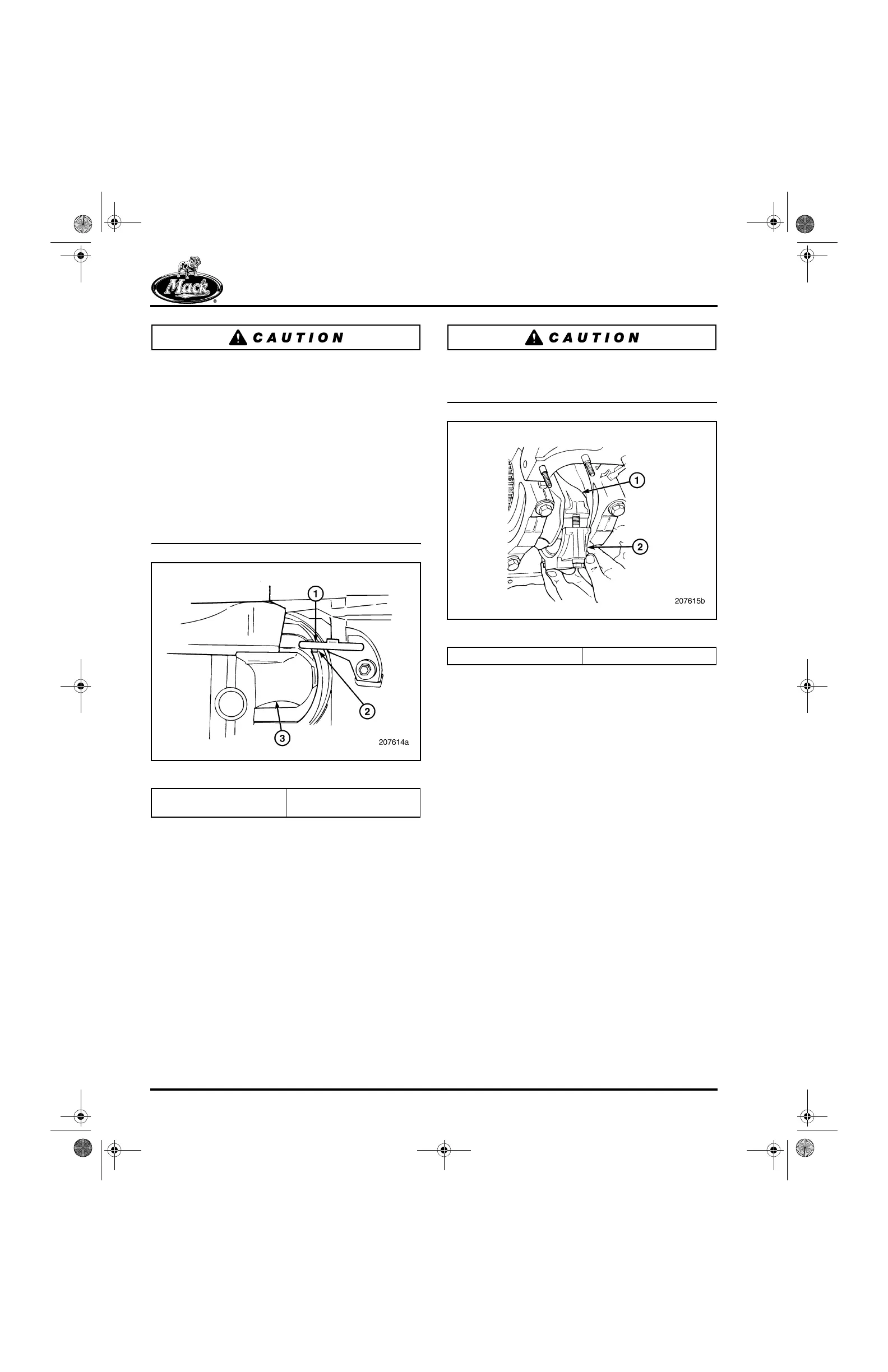
Before pushing the piston all the way down in the
sleeve, check to see that the piston cooling
nozzle is aligned with the nozzle clearance notch
provided in the lower end of the piston skirt as
shown in Figure 332. Damage to piston or spray
nozzle may result if it is not aligned.
332
Figure 332 — Piston Skirt/Cooling Nozzle Alignment
12. Align the rod with the crankshaft journal and
continue pushing the piston into the sleeve
while guiding the rod end to clear the piston
cooling nozzle and seat properly on the
crankshaft journal.
13. Ensure that the correct rod bearing lower
insert (matched to upper insert) and the
alignment sleeves are positioned in the
bearing cap.
14. Begin by installing the bearing cap at the
No. 1 connecting rod journal (Figure 333)
and check Running Clearance following the
procedure later in this section. Repeat the
running clearance check following the
installation of each of the remaining five
pistons.
Running clearance must be checked after
installing each piston. Damage to the engine may
result if clearance is not within specification.
333
Figure 333 — Connecting Rod Cap Installation
15. Repeat the above steps to install the No. 6
piston.
16. Rotate the crankshaft so that the journals for
the No. 2 and No. 5 cylinders are at bottom
dead center and install the No. 2 and No. 5
pistons following the above steps.
17. Rotate the crankshaft so that the journals for
the No. 3 and No. 4 cylinders are at bottom
dead center and install the No. 3 and No. 4
pistons, again following the above steps.
RUNNING CLEARANCE CHECK
1. Place a section of Plastigage on the rod cap
bearing and place the cap and bearing in
position on the rod.
2. Apply a light coat of oil on the threads of the
rod cap capscrews and install the screws.
3. Angle torque the capscrews to 30 lb-ft
(41 N폷m) plus 90 degrees using torque angle
gauge set BT 91104, or equivalent.
1. Cooling Nozzle
2. Clearance Notch
3. Connecting Rod
1. Connecting Rod 2. Bearing Cap
5-111.bk Page 296 Monday, July 10, 2006 2:26 PM
 Loading...

