Page 322
REPAIR INSTRUCTIONS, PART 1
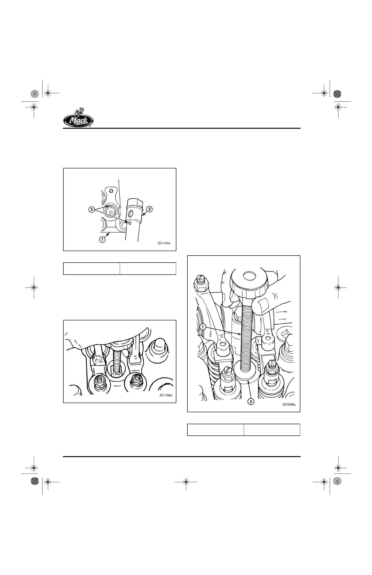
4. Insert the nozzle holder in the nozzle holder
sleeve. Be sure to align the locator pin in the
nozzle holder with the notch in the holder
sleeve to ensure inlet tube alignment. Refer
to Figure 373.
373
Figure 373 — Nozzle Holder Alignment
5. After ensuring that the nozzle holder locator
pin is properly aligned with the alignment
notch in the nozzle holder sleeve, push
downward on the handle of the installation
tool driving the nozzle holder into position.
Refer to Figure 374.
374
Figure 374 — Nozzle Holder Installation
6. Remove the tool from the nozzle holder and
insert the gauge block on the end of the tool
handle.
7. Insert the gauge block into the nozzle holder
sleeve bore. The gauge block should be
flush with the top surface of the cylinder
head nozzle sleeve bore. Refer to
Figure 375.
앫 If the gauge block is below the surface,
it may indicate that the gasket was
omitted.
앫 If the gauge block is too high, it may
indicate that there are two gaskets
installed under the nozzle holder, or the
nozzle holder has not been fully seated
in the sleeve.
앫 If a gauge block is not available,
measure the distance from the top
surface of the cylinder head sleeve
bore to the top of the nozzle holder.
The nominal measurement should be
0.564 inch (14.326 mm).
375
Figure 375 — Nozzle Holder Installation Check
1. Cylinder Head
2. Nozzle Holder
3. Locator Pin and Sleeve
Notch Must Align.
1. Nozzle Holder Puller
J 37093
2. Gauge Block
5-111.bk Page 322 Monday, July 10, 2006 2:26 PM