DESCRIPTION AND OPERATION
Page 21
EGR Valve — The poppet-type valve, operated
by hydraulic pressure from the engine oil system,
meters exhaust gas from the exhaust manifold
into the EGR circuit (Figure 9). The hydraulic
pressure is controlled by a solenoid within the
valve assembly reacting to signals from the
engine EECU. An internal spool valve diverts
hydraulic fluid, applying pressure to precisely
position the EGR poppet valve for control of
exhaust gas circulated through the engine. The
poppet valve has two sealing surfaces on a
common shaft to draw gases from the front and
rear sections of the manifold simultaneously.
The center section of the exhaust manifold
(Figure 15) is redesigned with mounting surfaces
for the EGR valve and turbocharger. The valve,
which is mounted on top the center section of the
manifold, is a non-serviceable unit. If a failure
should occur in any part of the valve, the valve
must be replaced as an assembly.
9
Figure 9 — EGR Valve
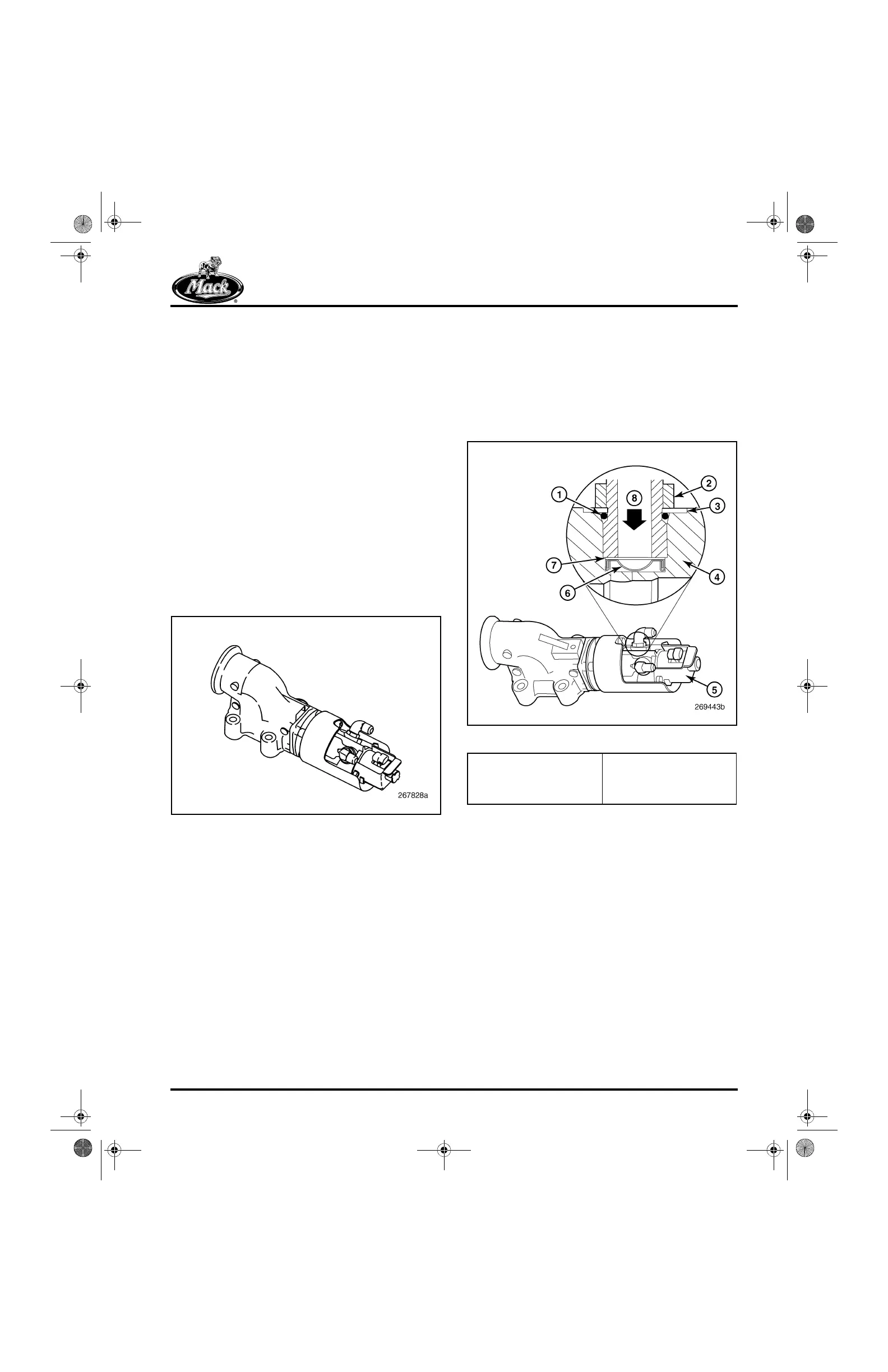
For current production (starting in March 2004),
the design of the EGR control valve shaft seal
has been changed to prevent contaminants from
entering and damaging the oil seal. Additionally,
a filter screen has been added to the oil inlet port
(Figure 10). The screen and a wave washer are
retained in the inlet port counterbore by the oil
inlet fitting.
10
Figure 10 — EGR Valve Oil Inlet Filter Screen
1. O-Ring
2. Fitting Jam Nut
3. Integral Washer
4. Valve Body
5. Part Number Location
6. Filter Screen
7. Wave Washer
8. Oil Flow Direction
5-111.bk Page 21 Monday, July 10, 2006 2:26 PM