Page 22
DESCRIPTION AND OPERATION
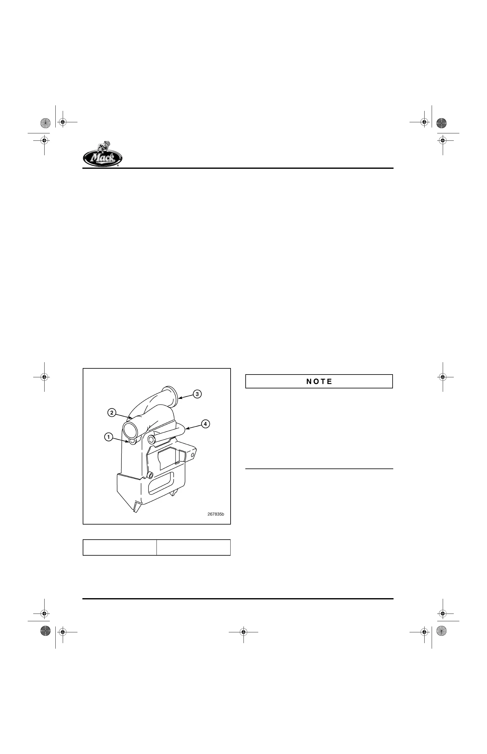
EGR Cooler — The cooler (Figure 11) is a
stainless steel assembly mounted on the lower
right side of the cylinder block. Hot exhaust gases
enter the cooler making two passes through the
core. Entering gases flow down through the outer
core half and up through the inner half to exit at
the top. Coolant flowing directly from the water
pump makes three passes through the core.
Entering at the rear, coolant is channelled
forward through the top part of the core, then
down and back through the bottom part, and
finally up and forward for one more pass through
the top before exiting at the front. This flow
pattern achieves the greatest cooling effect while
maintaining coolant temperatures below the
boiling point.
A petcock is located at the bottom rear corner of
the cooler for draining the cooler when it is to be
removed for service. While there are no specific
service requirements for the cooler, it is essential
for coolant quality to be maintained to keep the
core from becoming blocked. Also, prolonged
idling can cause carbon buildup and blockage
within the core and should be avoided.
11
Figure 11 — EGR Cooler
EGR MASS Flow System Tubes and
Clamps — A one-piece, 2-inch (51 mm) diameter
tube is used to connect the EGR valve to the
cooler on the hot side of the system. On the cool
side of the system, a 1.5-inch (38 mm) diameter
one-piece tube arrangement is used for routing
the exhaust gases from the cooler to the mixer
tube on the inlet manifold. The upper portion of
the one-piece tube is fitted with the EGR MASS
Flow sensors that provide system information to
the EECU.
Current production now consists of a one-piece
cool tube arrangement and a revised mounting
system (Figure 12). Hose connections with
constant tension-style clamps are used at both
ends, eliminating the bellows sections as used
with the two-piece arrangement. Coupling
adapters are used in combination with the hoses
to complete the connections on engines with
flange-style cool tube ports on the mixer tube and
EGR cooler. On later-production engines, the
flange-style tube ports on the EGR cooler and
mixer tube are redesigned to accept the hose
connections directly, eliminating the need for the
coupling adapters.
The EGR MASS Flow sensors are an integral
part of both EGR gas cool tube arrangements
and cannot be removed. The sensors are
calibrated specifically to the EGR cool tube and
the EGR MASS Flow System module. If
replacement is required, the entire cool tube
assembly with its integral sensors and connecting
harnesses MUST BE replaced along with the
MASS Flow System module attached to the back
of the EECU cooling plate.
1. Coolant Outlet
2. Gas Outlet
3. Gas Inlet
4. Coolant Inlet
5-111.bk Page 22 Monday, July 10, 2006 2:26 PM