REPAIR INSTRUCTIONS, PART 1
Page 329
4. Lubricate the threads and undersides of the
heads of the rocker arm capscrews with
clean engine oil. Place the capscrews in the
mounting brackets and tighten by hand as
much as possible.
Effective 4th quarter 2005, a revised rocker arm
shaft mounting bolt (part No. 416GC23M) was
implemented into production. These bolts are
available through the MACK Parts System, and
should be used as the replacement bolt anytime
the rocker arm shaft bolts are removed.
If any rocker arm shaft mounting bolts were found
to be broken at disassembly, all 12 mounting
bolts MUST be replaced.
5. Again, depress each rocker arm adjusting
screw so that the ball end is down and in full
contact with the push rod cup. As each
rocker arm is depressed, rotate the push rod
to ensure proper installation.
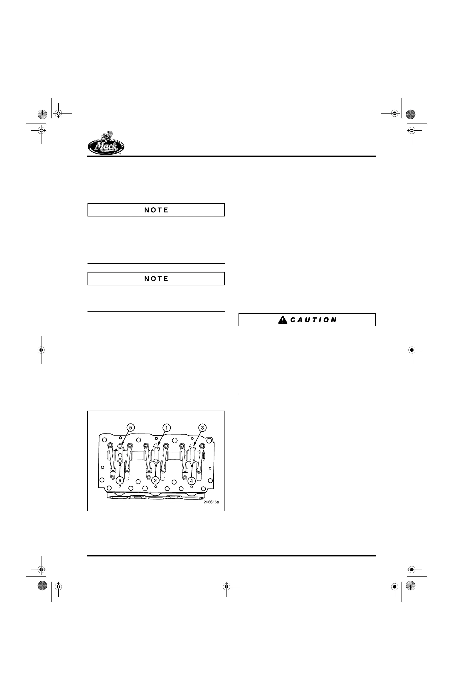
6. Beginning at the center mounting bracket
with capscrew No. 1, tighten the capscrews
in the sequence shown in Figure 385.
Tighten the capscrews to the specified
torque, 45 lb-ft (61 N폷m), using an accurately
calibrated torque wrench J 24407, or
equivalent.
385
Figure 385 — Rocker Shaft Assembly Capscrew
Tightening Sequence
7. Adjust the valve lash to the specified
settings. Refer to “Valve Yoke and Valve
Lash Adjustments” in the ENGINE SETUP
AND ADJUSTMENTS section.
INSTALLATION (J-TECH™ BRAKE-EQUIPPED
ENGINES)
Refer to Figure 387.
1. Make sure the oil supply screw is in position
on the rocker arm mounting bracket for each
cylinder head and tightened to specification,
5 lb-ft (6.8 N폷m).
2. Make sure that all 12 push rods are properly
seated in the respective lifter sockets with
standard push rods at the inlet valve
locations and spring-loaded at the exhaust
valve locations. Use care when checking the
push rod seating. DO NOT drop the push
rods onto the lifters.
Make sure the rocker adjusting screws are turned
completely upward into the rocker arms before
installing the rocker shaft or engine brake units on
the engine. If this is not done, tightening the
mounting bolts for the rocker shafts or engine
brake units, or rotating the engine to adjust the
valves, can bend the push rods or subject the
ceramic rollers to excessive loads which can
damage or break the rollers.
3. Place the rocker shaft assemblies in position
on the cylinder heads, making sure that the
mounting screw holes are properly aligned.
Depress the adjusting screw end of each
rocker arm so that the adjusting screw ball
end is down and in full contact with the push
rod cup. With the rocker arm depressed in
this fashion, rotate each push rod to be sure
it is properly seated in the lifter cup and at
the rocker arm adjusting screw.
5-111.bk Page 329 Monday, July 10, 2006 2:26 PM