Page 330
REPAIR INSTRUCTIONS, PART 1
If the rocker shaft assembly is lifted off the
cylinder head anytime during the installation
procedure, either partially or completely, steps 2
and 3 above must be repeated. Not having the
rockers properly positioned as described in step 3
is the usual cause of a push rod being dislodged
from the lifter cup. If this should occur and not be
corrected, the ceramic roller will break when the
engine is rotated.
4. Loosen the three slave piston adjusting
screw jam nuts on each brake assembly and
back out the adjusting screws so that the
slave pistons are fully retracted into the
housings.
5. Carefully place each housing on the
appropriate rocker arm shaft assembly so
the oil supply screw engages the locating
hole in the brake housing.
6. Lubricate the threads of the brake housing
mounting bolts with clean engine oil and
install the bolts in the housing mounting bolt
holes. Ensure that the correct mounting
bolts are used:
Bolt P/N 416GC22M — use with housing
P/N 757GB58.
Bolt P/N 421GC314M — use with housing
P/Ns 757GB58A and 757GB58B.
7. Starting with the center pair of mounting
bolts, tighten all six bolts on each housing
just enough to seat the housing on the
rocker shaft brackets. Make sure the brake
housings come down level to avoid possible
damage to the rocker shaft brackets.
8. Again, depress each rocker arm adjusting
screw so that the ball end is down and in full
contact with the push rod cup. As each
rocker arm is depressed, rotate the push rod
to ensure proper installation.
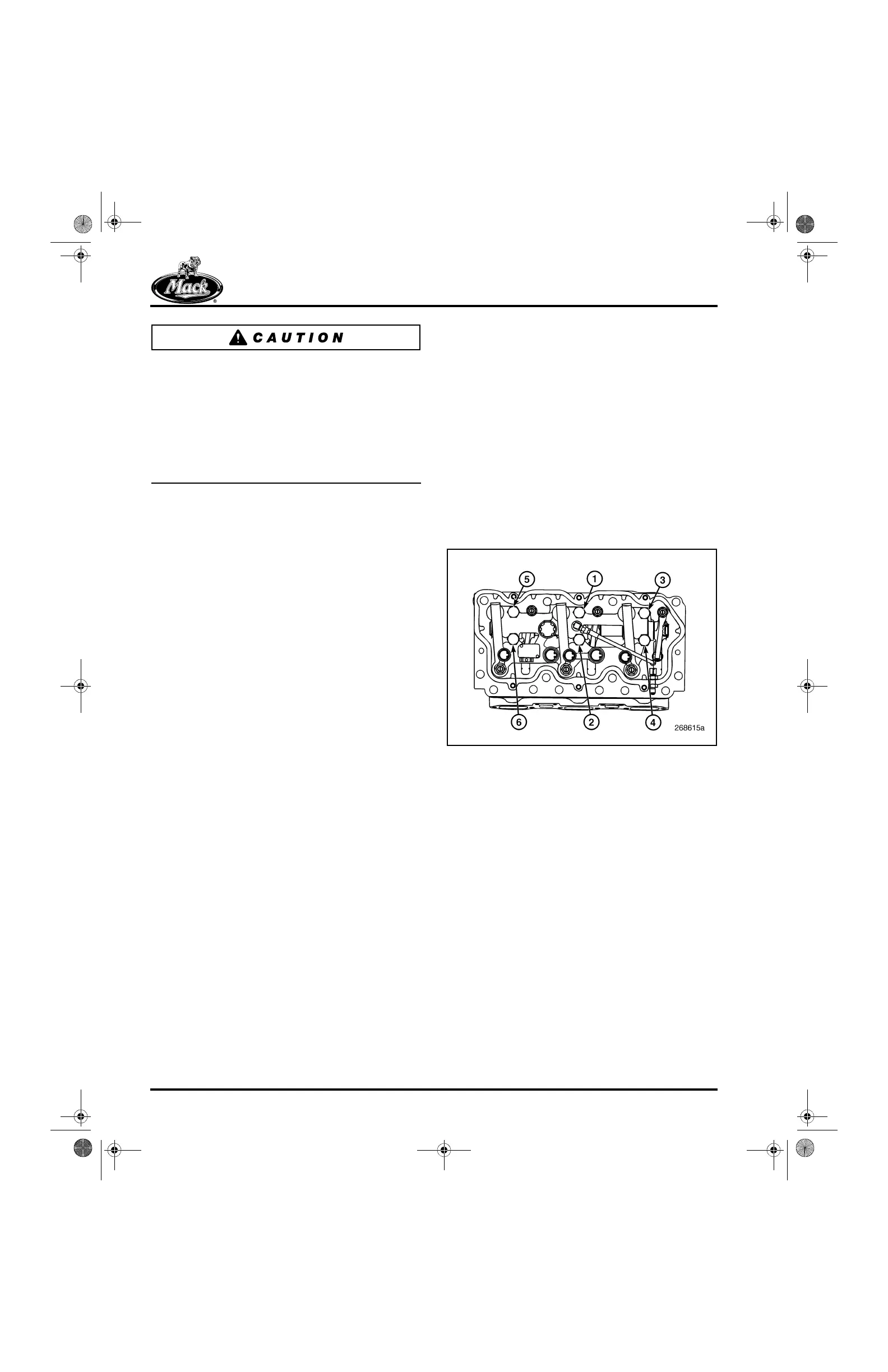
9. After each brake housing is seated on the
cylinder head, tighten the mounting bolts to
specification, 45 lb-ft (61 N폷m), in the
sequence shown (Figure 386).
386
Figure 386 — Engine Brake Assembly Mounting Bolt
Tightening Sequence
10. Adjust the valve lash to the specified
settings. Refer to “Valve Yoke, Valve Lash
and Slave Piston Adjustments” in the
ENGINE SETUP AND ADJUSTMENTS
section.
5-111.bk Page 330 Monday, July 10, 2006 2:26 PM