Page 332
REPAIR INSTRUCTIONS, PART 1
INSTALLATION (MACK POWERLEASH™
BRAKE-EQUIPPED ENGINES)
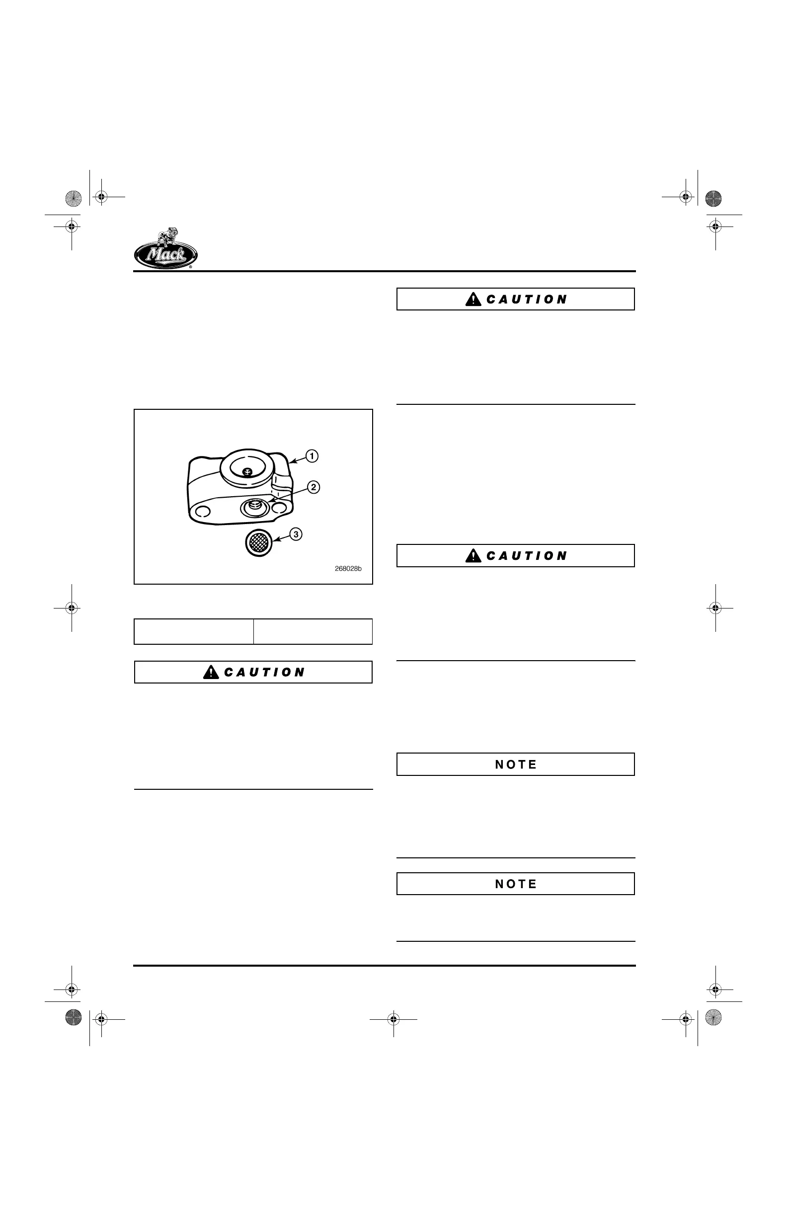
Before installing the PowerLeash™ rocker shaft,
verify that the oil supply screen is positioned in
the counterbore at the bottom of the front rocker
shaft mounting bracket. If the screen fits loosely
in the bore, use some grease to hold the screen
in place while the rocker shaft assembly is being
installed on the engine.
388
Figure 388 — Oil Supply Screen in Front Mounting
Bracket
If the screen should slip out of place during
installation of the rocker shaft assembly to the
engine, the screen edge may become pinched
between the rocker shaft mounting bracket and
the surface of the cylinder head. If this occurs,
broken hold-down bolts, a broken rocker shaft or
both can result with the possibility of major engine
damage.
1. Make sure all 12 push rods are properly
seated in the respective lifter sockets. When
installing push rods, use care to gently lower
them into position on the lifter cups. DO
NOT drop the push rods onto the lifters.
Make sure that all adjusting screws and brake
lash adjusting screws are screwed completely
upward into the rocker arms before installing the
rocker shaft on the engine. If this is not done,
tightening the mounting bolts for the rocker shafts
or rotating the engine to adjust the valves, can
bend the push rods.
2. Place the rocker shaft assemblies on the
cylinder heads and align the rocker bracket
mounting holes with the holes in the cylinder
head. Depress the adjusting screw end of
each rocker arm so that the adjusting screw
ball end is fully down into each push rod cup.
With the rocker arm depressed, rotate each
push rod to be sure it is fully seated in the
lifter cup and at the rocker arm adjusting
screw.
If the rocker shaft assembly is lifted off, or
partially lifted off the cylinder head at anytime
during the installation procedures, steps 1 and 2
above must be repeated. Not having the rockers
positioned as described in step 2 above, or lifting
the rockers are the usual causes of dislodging a
push rod from the lifter cup.
3. Lubricate the threads of the rocker shaft
mounting bracket bolts and the undersides
of the bolt heads with clean engine oil. Place
the bolts into the mounting brackets, then
start each bolt by hand and tighten by hand
as much as possible.
Effective 4th quarter 2005, a revised rocker arm
shaft mounting bolt (part No. 416GC23M) was
implemented into production. These bolts are
available through the MACK Parts System, and
should be used as the replacement bolt anytime
the rocker arm shaft bolts are removed.
If any rocker arm shaft mounting bolts were found
to be broken at disassembly, all 12 mounting
bolts MUST be replaced.
1. Front Mounting Bracket
2. Oil Supply Port
3. Oil Supply Screen
5-111.bk Page 332 Monday, July 10, 2006 2:26 PM