Page 346
REPAIR INSTRUCTIONS, PART 1
1. With the water pump housing positioned on
a bench with the cylinder block/head
mounting surface facing up, place a new
O-ring in the groove at the coolant inlet
flange. Use MACK Code 442 grease or any
quality O-ring grease to hold the O-rings in
place for assembly.
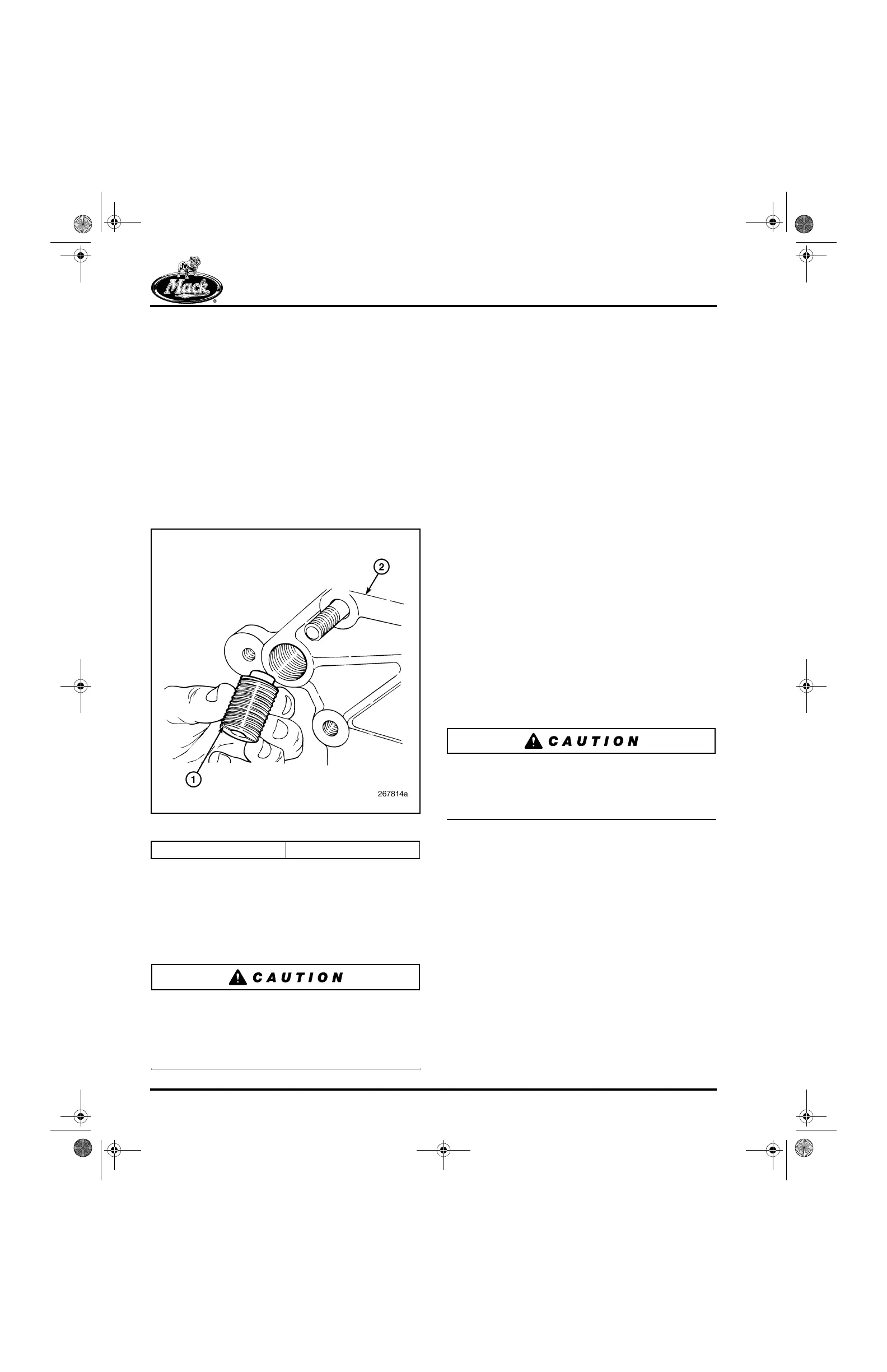
2. Stand the housing on edge and from the
front, start the threaded inserts into the
mounting bores at the top of the housing
(Figure 407). Turn them in until the collar of
each protrudes from the back side and the
shoulder is 0.020-inch (0.5 mm) under to
flush with the back side.
407
Figure 407 — Threaded Insert Installation
3. Again, with the housing standing on edge
and from the front, insert two mounting
capscrews and washers into the
mid-position bolt holes. The two mid-position
holes are slightly smaller to serve as pilot
holes for installation.
The water pump cartridge assembly and water
pump housing mounting bolts should not be
lubricated before installation. Instead, apply
thread sealing compound to all cartridge
assembly and housing capscrews.
4. Place the housing in position at the front of
the cylinder block and start the mid-position
capscrews into the block, far enough to
secure the housing from falling. The housing
should be free to move slightly back for
installation of the engine lifting bracket in the
following steps.
5. Place the engine lifting bracket in position
(bend angle facing forward) between the
housing and cylinder head (Figure 406).
Make sure the bracket mounting holes clear
and slip into position on the insert collars.
6. Push the housing against the block and
hand-tighten the mid-position mounting
capscrews.
7. Install the two mounting capscrews and
washers in the low-position mounting holes,
hand-tight.
8. Make sure the lifting bracket mounting holes
are properly positioned on the insert collars
and then tighten the mid-position and
low-position capscrews to specification,
69 lb-ft (94 N폷m), in sequence A, B, C, D
shown in Figure 406.
9. Using a suitable slotted socket, tighten the
two threaded inserts to specification, 50 lb-in
(5.6 N폷m).
Insert is to be tightened to 51 lb-in (5.6 N
폷
m). Use
care not to overtighten the threaded inserts.
Doing so could place undue stress on the
housing, causing it to bow and eventually break.
10. Install the remaining two mounting
capscrews (no washers) through the
threaded inserts and tighten to specification,
40 lb-ft (55 N폷m).
1. Threaded Insert 2. Pump Housing
5-111.bk Page 346 Monday, July 10, 2006 2:26 PM