REPAIR INSTRUCTIONS, PART 1
Page 347
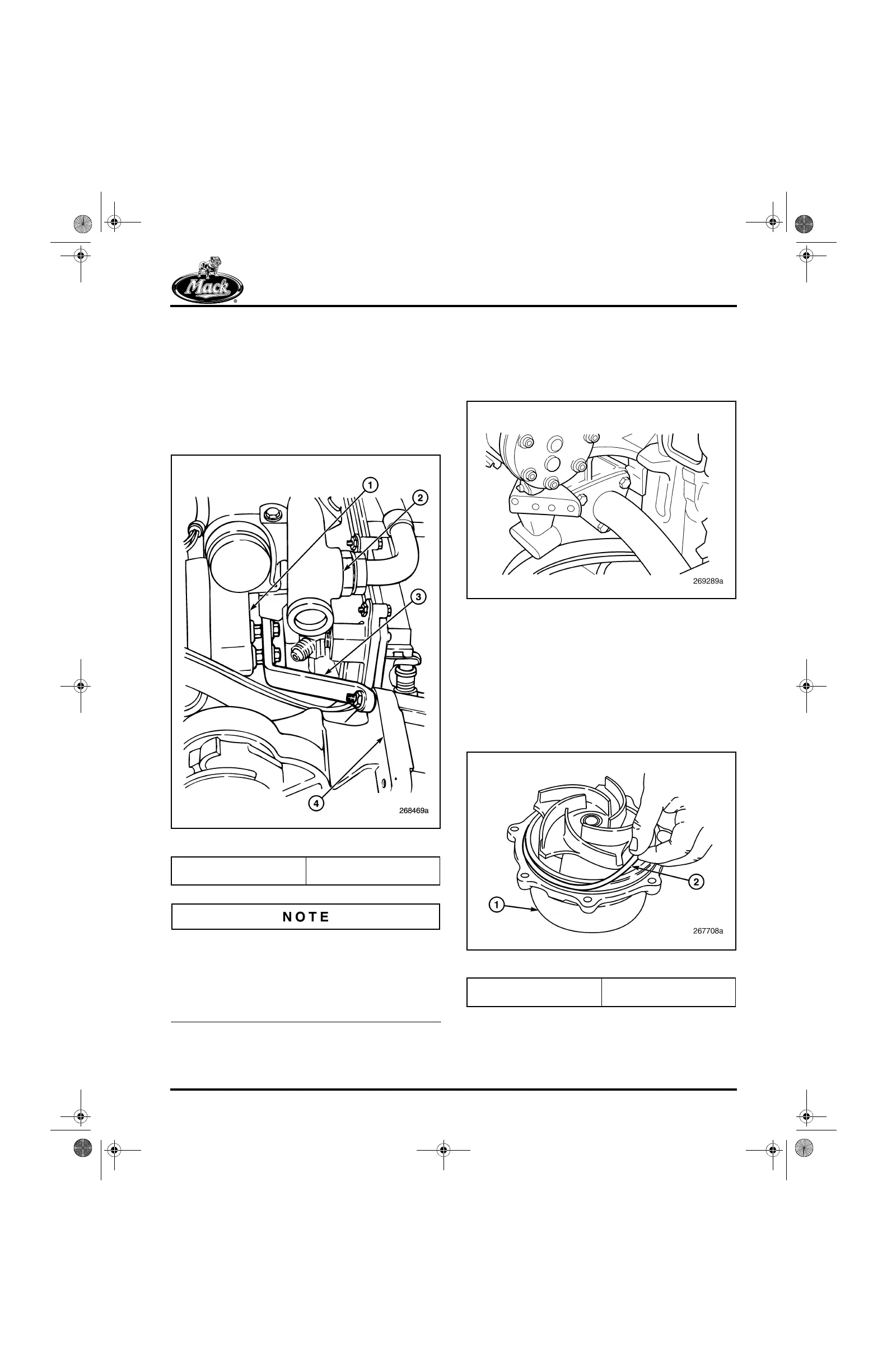
11. Position the water pump stiffening bracket
over the two studs at the forward position of
the coolant manifold. At the same time,
position the forward section of the stiffening
bracket over the backside of the A/C
compressor upper rear mounting stud.
Install the three M8 flanged nuts on the
stiffening bracket and tighten to 20 lb-ft
(27 N폷m). Refer to Figure 408.
408
Figure 408 — Stiffening Bracket
It is important not to install the stiffening bracket
before the water pump housing fasteners have
been torqued in place. Installing the bracket
before the housing capscrews have been
tightened may put undue stress on the top of the
housing and cause damage to the housing.
12. Install the coolant inlet tube (from the oil
cooler) on the inlet port at the back of the
water pump on the left side of the engine
(Figure 409). Tighten the capscrews to
40 lb-ft (55 N폷m).
409
Figure 409 — Coolant Inlet Tube Mounting (Back of
Front-Redesign Water Pump)
13. Connect the EGR cooler coolant supply
hose to the water pump on the right side of
the engine.
14. If the pump cartridge assembly has been
removed, install a new O-ring on the water
pump cartridge assembly mounting flange
(Figure 410).
410
Figure 410 — O-Ring Installation
1. Coolant Manifold
2. Thermostat Housing
3. Stiffening Bracket
4. Water Pump Housing
1. Water Pump Cartridge
Assembly
2. O-Ring
5-111.bk Page 347 Monday, July 10, 2006 2:26 PM