DESCRIPTION AND OPERATION
Page 25
EGR MASS Flow System — As mentioned
earlier, the EGR MASS Flow System (MFS)
consists of a one-piece cool tube, two MASS flow
sensors and the MFS electronic module. The
MASS flow sensors are permanently mounted in
the EGR tube bosses, and harnesses connect
the sensors to the MFS electronic module.
When the MASS flow system is calibrated during
the manufacturing process, one or both of the
sensor retaining nuts are welded to the boss
threads. Neither of the sensors is to be removed
from the tube, or tampered with in any way.
Additionally, the MASS flow system electronic
module is calibrated to the tube and sensor
assembly.
The entire cool tube with the EGR MASS Flow
sensors must be replaced as an assembly along
with replacement of the EGR MASS Flow control
module should any part, tube, sensor or module
fail.
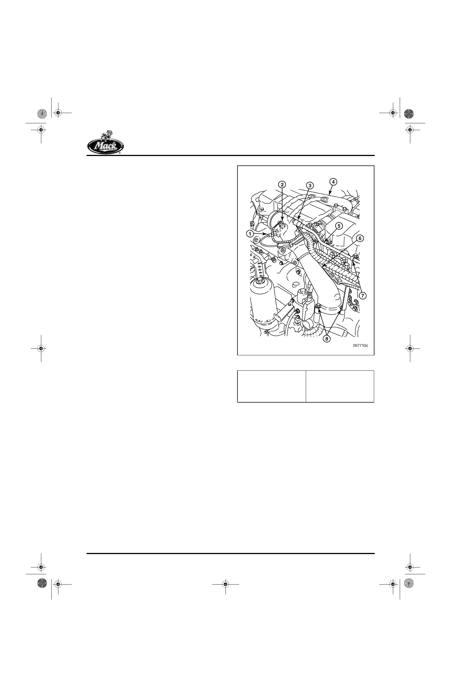
EGR Mixer Tube — The EGR mixer tube is an
assembly attached to a port at the top rear of the
inlet manifold. Here, cooled exhaust gases are
blended with the charged inlet air entering the
inlet manifold and cylinders. The tube is a
cast-aluminum assembly with ports for the
CMCAC temperature and pressure sensors, and
the boost air pressure relief valve (Figure 14).
14
Figure 14 — EGR Mixer Tube
1. Temperature Sensor
2. Pressure Sensor
3. Boost Relief Valve
4. EGR Cool Tube
5. Boost Relief-to-Exhaust
Tube
6. EGR Mixer Tube
7. Tube Clamp
8. Mixer Tube Capscrews
5-111.bk Page 25 Monday, July 10, 2006 2:26 PM