DESCRIPTION AND OPERATION
Page 29
COOLING SYSTEM CHANGES
Redesigned Water Pump Housing
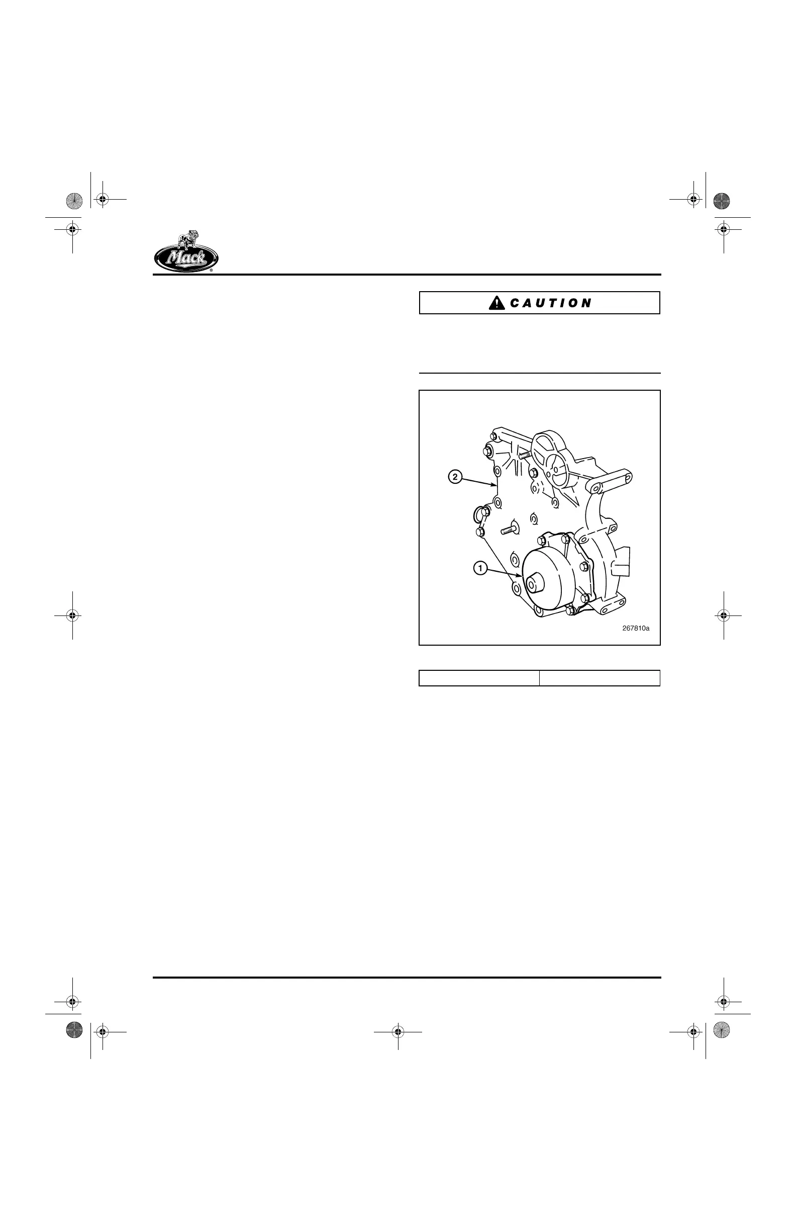
Assembly — The water pump housing is a
completely new assembly (Figure 20) covering
the upper part of the cylinder block just above the
front timing cover. With the new assembly,
coolant flow is increased by 10 percent to meet
the additional cooling capacity required by the
EGR system. Coolant flows through the housing
and into the cylinder block and EGR cooler
circuits. These circuits run in parallel, circulating
back to the inlet side of the oil cooler.
Mounted on the left side of the water pump
housing is the separately serviceable pump
cartridge with pulley and impeller. With the
cartridge offset to the left side, the fan drive
assembly and belt tensioners can be mounted
directly at the center in one of several different
vertical locations best suited for a vehicle
configuration. Just behind the cartridge at the left
rear side of the housing is a mounting pad for the
coolant conditioner.
Sealing of the cartridge to the complete water
pump housing is accomplished with an O-ring.
The complete water pump housing assembly is
bolted to the front of the cylinder block and
cylinder head. Once in place, there are no service
requirements for the assembly.
When replacing or reinstalling a removed
assembly, it is critical that the setup procedures
are followed to prevent the housing from being
stressed and breaking.
20
Figure 20 — Water Pump Housing Assembly
1. Water Pump Cartridge 2. Water Pump Housing
5-111.bk Page 29 Monday, July 10, 2006 2:26 PM