Page 30
DESCRIPTION AND OPERATION
Dual Thermostat Housing — To get the
additional cooling capacity and flow requirements
for the EGR system, two thermostats are used.
The thermostats are mounted in a new aluminum
housing bolted to the top of the coolant (water)
manifold (Figure 21). Sealing of the thermostat
housing to the coolant manifold is accomplished
by rubber seals attached to the bottom of each
thermostat. No other gasket or sealant is
required. A lip-type seal is pressed into the
thermostat housing to prevent leakage past the
thermostat barrel. Stainless steel inserts pressed
into the housing eliminate any wear that
otherwise would be caused by the thermostats as
they open and close during operation.
21
Figure 21 — Dual Thermostat Housing
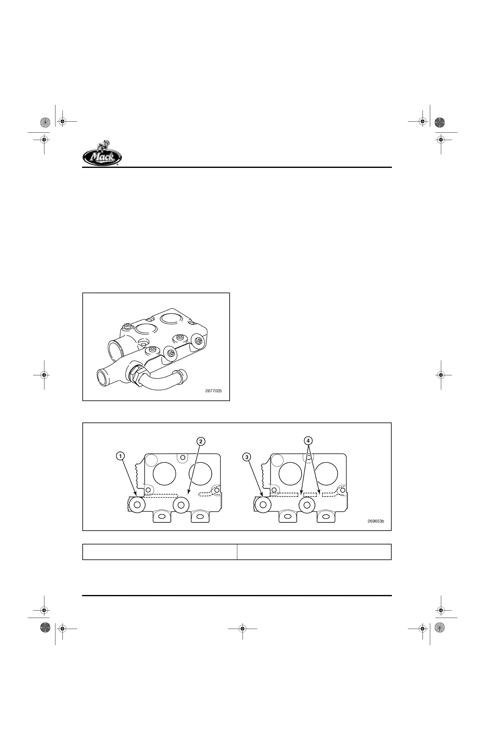
Dual Thermostat Housing Revisions for 2004
The thermostat housing has an internal cast wall
which divides the thermostat housing into two
sections, the thermostat section and the bypass
section.
The original thermostat housings had two
1/2-inch diameter holes cast into the wall
between the two sections. The two 1/2-inch
diameter holes restrict coolant flow so that a
pressure differential is created between the two
sections. This design allowed the cab heater
coolant return lines to be connected to the
thermostat housing bypass section.
Beginning second quarter of 2004, a thermostat
housing having a larger opening in the divider
wall was phased into production. This change
reduces the pressure differential between the
thermostat section and the bypass section, which
provides improved water pump seal life and
reduced cooling system noise and vibration.
With the thermostat housing positive differential
reduced, the cab heater coolant return lines can
no longer be connected to the revised thermostat
housing or inadequate coolant flow through the
heater would result. Therefore, the cab heater
and optional fuel heater return lines have been
moved to the radiator lower tube for highway
chassis.
22
Figure 22 — Thermostat Housing Comparison
1. Thermostat Housing (2nd Quarter 04 and Later)
2. Enlarged Opening in Housing Divider Wall
3. Thermostat Housing (Prior to 2nd Quarter 04)
4. Two 1/2-Inch Holes in Housing Divider Wall
5-111.bk Page 30 Monday, July 10, 2006 2:26 PM