REPAIR INSTRUCTIONS, PART 2
Page 429
521
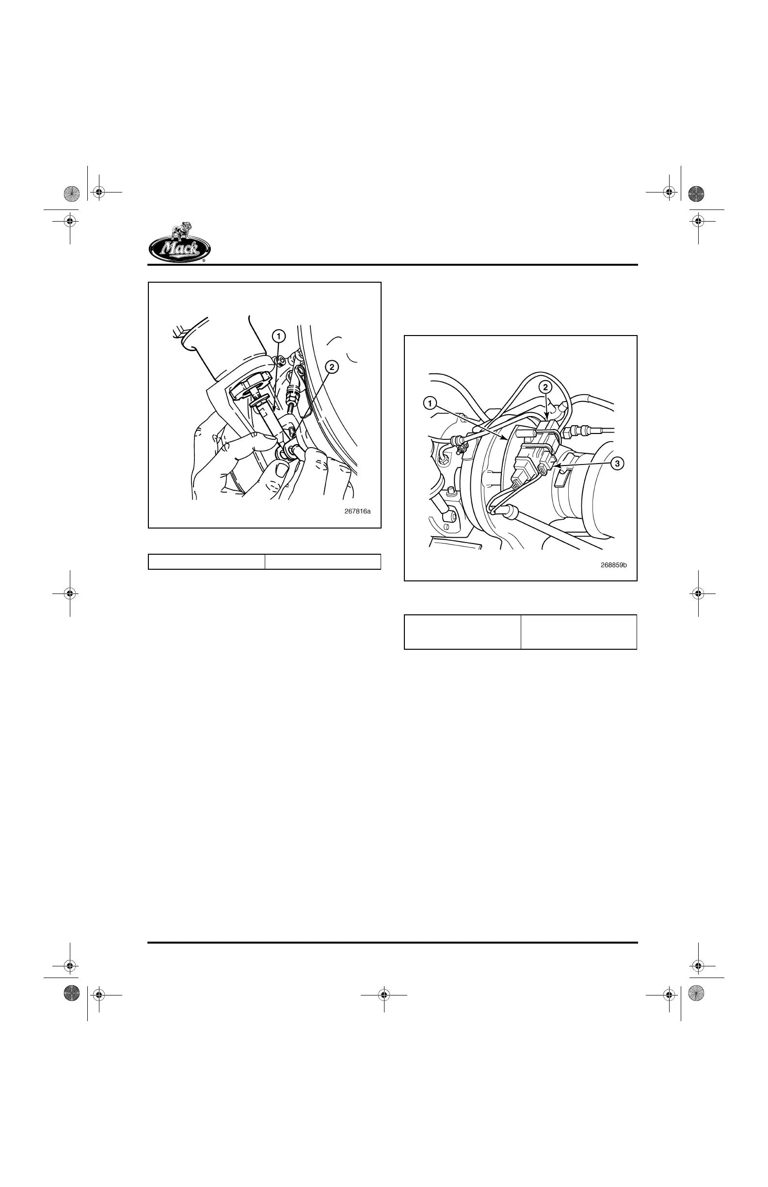
Figure 521 — Vane Operating Lever Connection
4. Release the air pressure and disconnect the
shop air line.
5. Cut the two tie straps that attach the
turbocharger wheel speed sensor harness
connector to the top of the vane position
sensor module at the front of the
turbocharger compressor housing (refer to
Figure 522). Note the way the position
sensor and wheel speed sensor wires are
routed, and also note the orientation of the
harness clamp.
6. Loosen and remove the nut and washer that
secures the wire harness clamp to the
turbocharger compressor housing V-band
clamp, then remove the clamp.
7. Remove the three 6 mm Allen-head bolts
and washers that secure the position sensor
connector and thermal isolation plate
assembly to the compressor housing.
522
Figure 522 — Position Sensor Module and Thermal
Isolation Plate Assembly
8. Using spanner wrench J 47019, remove the
spanner nut (Figure 523) that retains the
actuator to the actuator mounting flange,
then remove the actuator/position
sensor/isolation plate assembly from the
mounting flange.
1. Actuator Rod 2. Vane Operating Lever
1. Thermal Isolation Plate
2. Vane Position Sensor
Module
3. Wheel Speed Sensor
Harness Connector
5-111.bk Page 429 Monday, July 10, 2006 2:26 PM