Page 430
REPAIR INSTRUCTIONS, PART 2
523
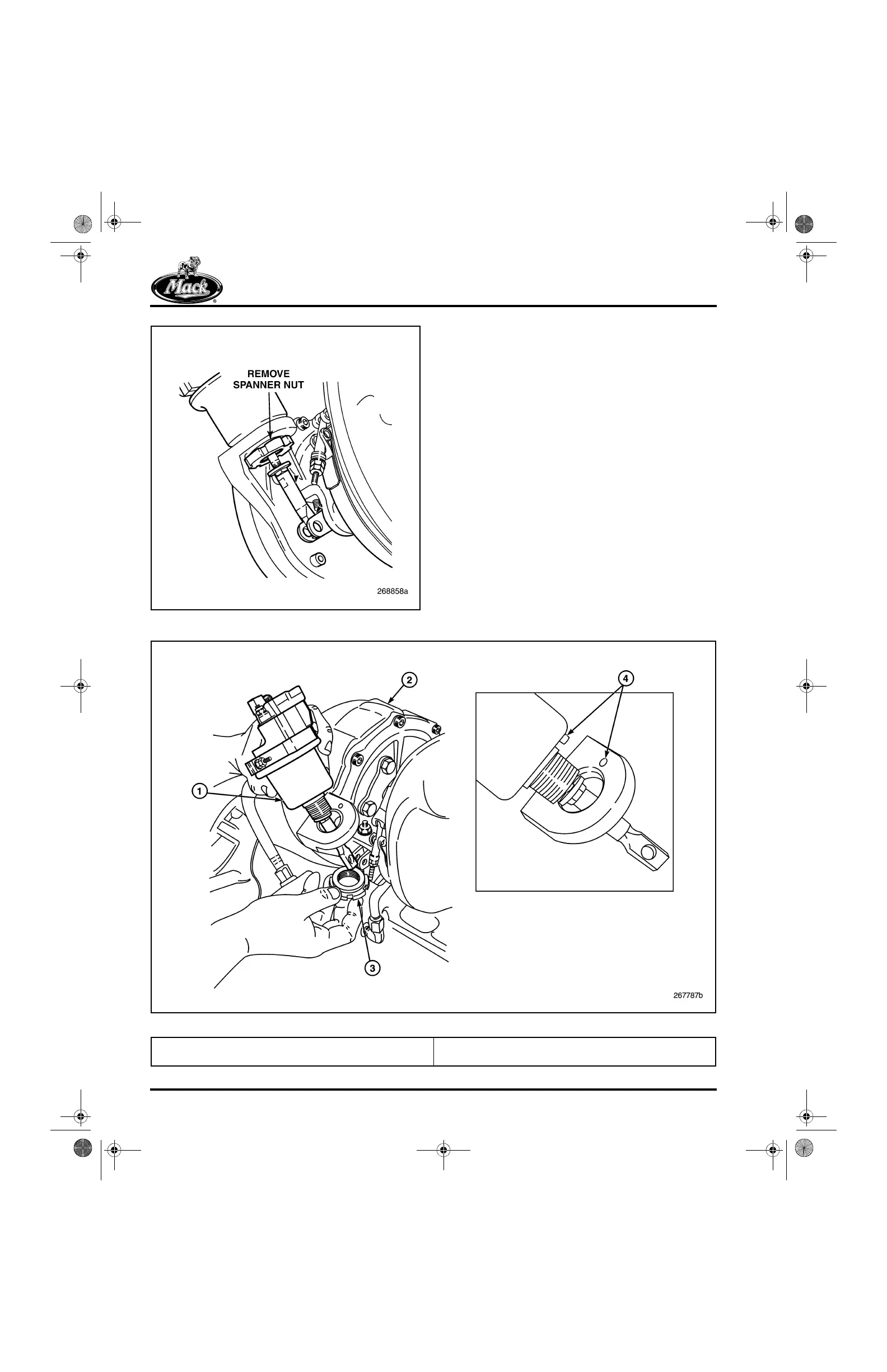
Figure 523 — Actuator Assembly Removal
VTG ACTUATOR INSTALLATION
1. Place the VTG actuator assembly in position
on the mounting flange at the center of the
turbocharger. Make sure the alignment pin is
positioned in the hole on the flange
(Figure 524).
524
Figure 524 — VTG Actuator Installation
1. VTG Actuator Assembly
2. Turbocharger Assembly
3. Actuator Spanner Nut
4. Alignment Pin/Hole
5-111.bk Page 430 Monday, July 10, 2006 2:26 PM