REPAIR INSTRUCTIONS, PART 2
Page 431
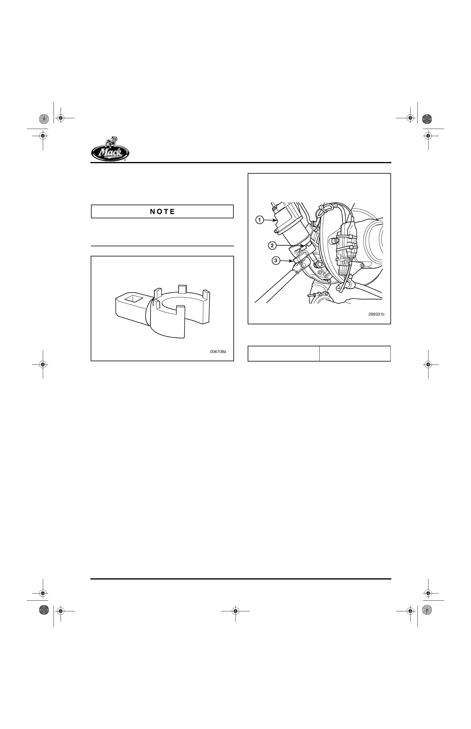
2. Using spanner wrench J 47019, install the
spanner nut securing the actuator assembly
to the mounting flange. Tighten the nut to
specification, 92 lb-ft (125 N폷m).
To ensure that the spanner nut is tightened to the
proper torque value, spanner wrench J 47019
(Figure 525) is required.
525
Figure 525 — Spanner Wrench (J 47019)
3. When tightening the spanner nut, make sure
that the spanner wrench fully engages the
nut as shown in the Figure 526. If not
properly engaged, the wrench tangs can be
damaged if the wrench slips out of
engagement when torque is applied.
526
Figure 526 — Using Spanner Wrench to Tighten
Spanner Nut
4. Adjust and verify actuator rod length as
follows:
a. Manually move the VTG lever arm
clevis against the upper stop (vanes
fully opened).
b. With the actuator rod fully retracted and
the lever arm clevis against the upper
stop, note the alignment of the hole in
the lever arm clevis with the hole in the
actuator rod end. If not in alignment,
release the lever arm clevis and allow it
to rest on the lower stop, then loosen
the actuator rod end jam nut and adjust
the rod end until the holes are in
alignment (when the lever arm clevis is
against the upper stop). The adjusted
actuator rod length can be verified by
inserting the rod end pin and making
sure the clevis remains against the
upper stop.
1. VTG Actuator Assembly
2. Spanner Nut
3. Spanner Wrench
(J 47019)
5-111.bk Page 431 Monday, July 10, 2006 2:26 PM