Page 432
REPAIR INSTRUCTIONS, PART 2
527
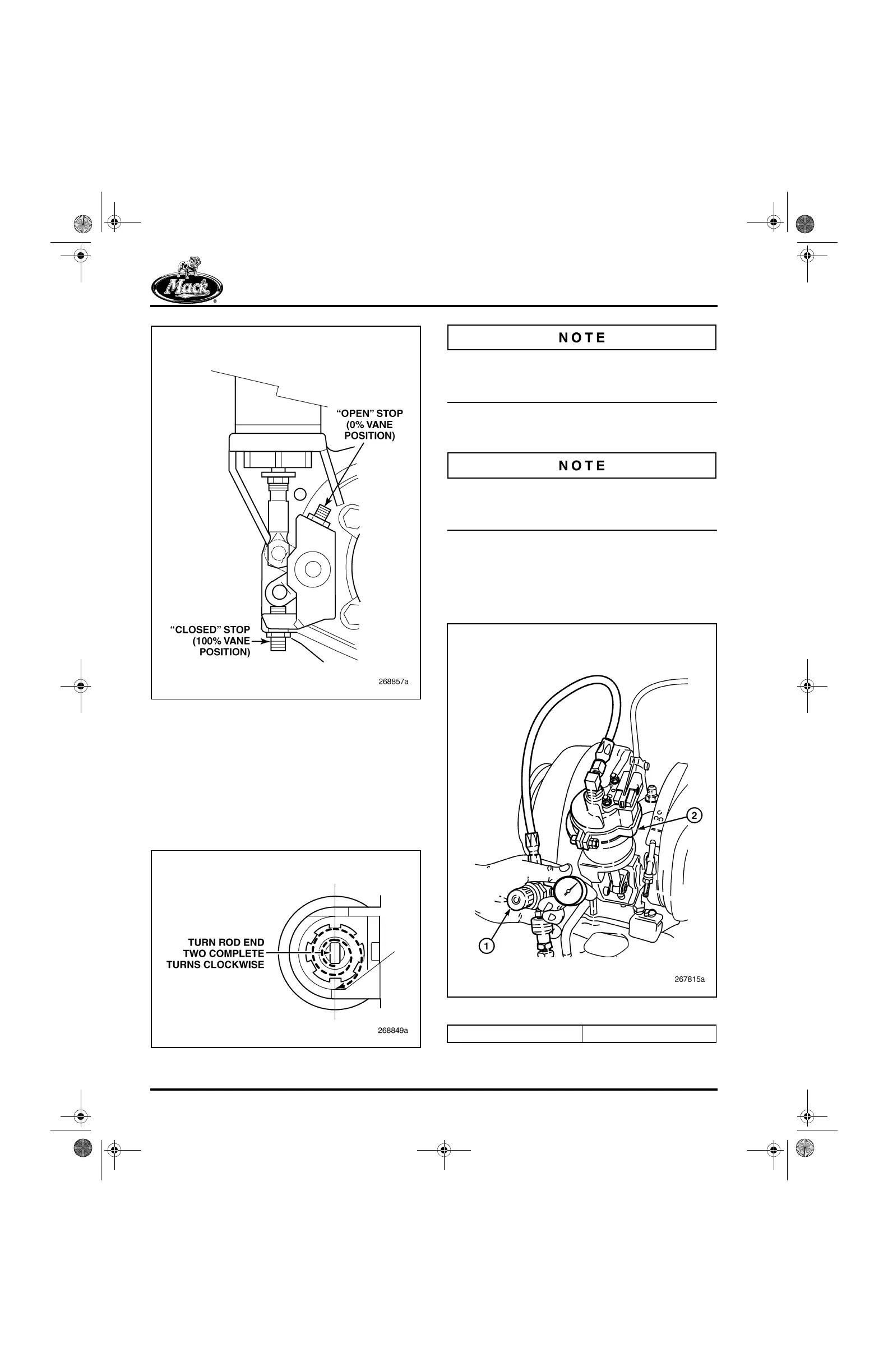
Figure 527 — Rod End-to-Lever Arm Clevis Alignment
c. Once the adjusted actuator rod length
has been obtained, release the lever
arm clevis and allow it to rest against
the lower stop. Turn the rod end two
complete turns clockwise (when viewed
from the rod end side of the actuator
assembly) to shorten the actuator rod
length.
528
Figure 528 — Completing Rod End Adjustment
Step c must be completed or the actuator will be
out of range and cause a fault to be logged in the
V-MAC
®
system.
d. Using an open-end wrench on the two
flats on the rod end, tighten the jam nut.
The actuator rod end must be held with an
open-end wrench to avoid torsional damage to
the actuator diaphragm.
5. Connect a regulated shop air supply (with a
pressure gauge) to the air fitting at the top of
the actuator assembly (Figure 529) and
apply 40–60 psi of air pressure to extend the
actuator rod downward.
529
Figure 529 — Air Pressure Application
1. Shop Air Supply Line 2. VTG Actuator Assembly
5-111.bk Page 432 Monday, July 10, 2006 2:26 PM