REPAIR INSTRUCTIONS, PART 2
Page 433
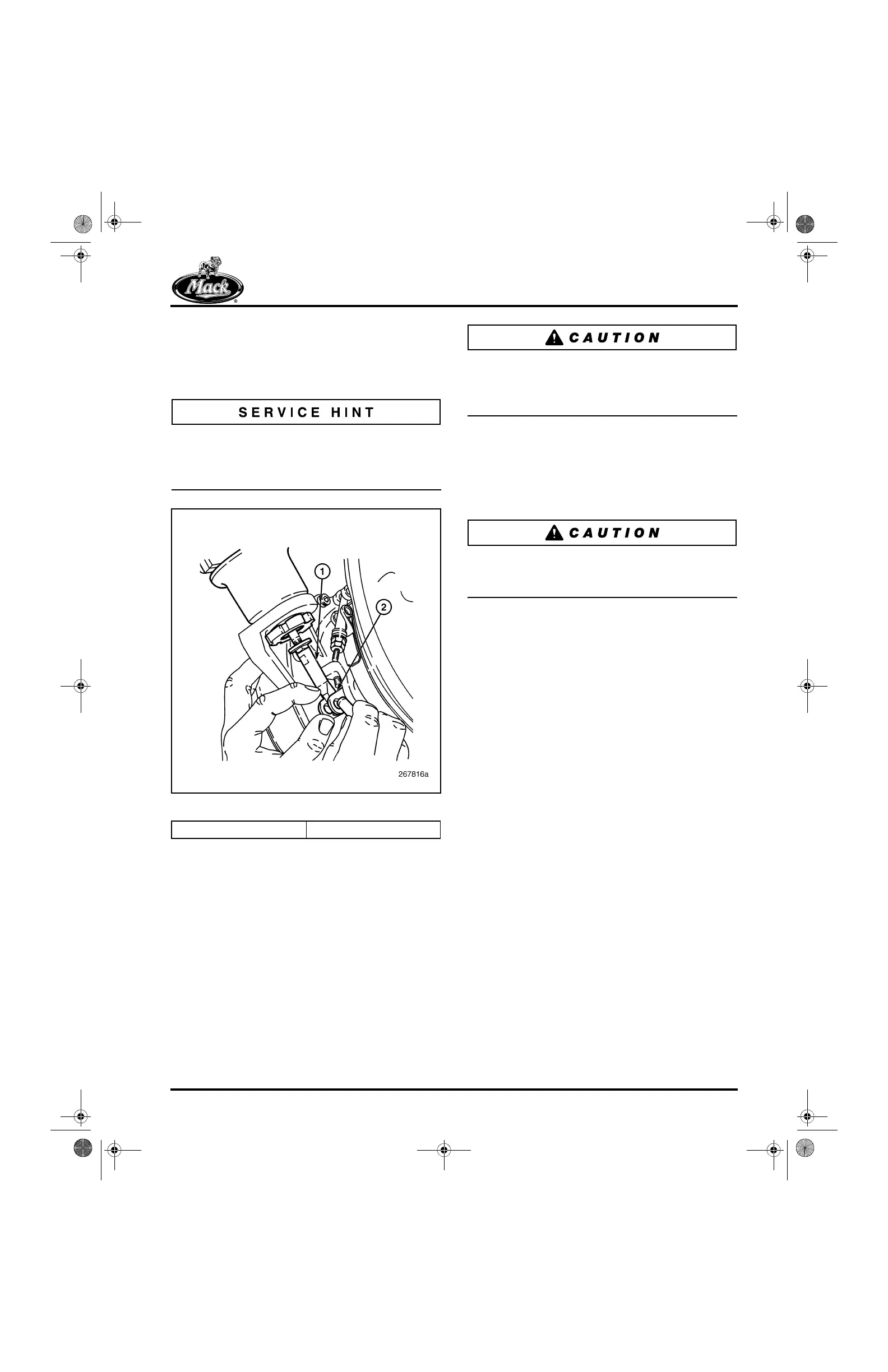
6. With air pressure applied and the actuator
rod extended, move the lever arm clevis to
align the hole in the clevis with the hole in
the rod end and insert the clevis pin
(Figure 530).
Because of preload, it is easier to install the pin
through the vane lever arm clevis and actuator
rod hole when the rod is in an extended position
and not retracted into the housing.
530
Figure 530 — Vane Operating Lever Connection
7. Set the pressure regulator to 0 psi. The
actuator rod should retract and pull the vane
operating lever against the upper stop
(vanes open).
8. Adjust the regulator to apply 95–100 psi of
shop air pressure to the actuator. The
actuator rod should extend, pushing the
vane operating lever down against the lower
stop (vanes fully closed).
Use care in applying air pressure to the actuator
assembly. DO NOT apply more than 100 psi.
Pressures greater than 100 psi will result in
damage to the actuator.
9. Verify that the lever arm clevis moves fully
from stop-to-stop. Then, carefully tighten the
actuator rod end jam nut to 106 lb-in
(12 N폷m) while using an open-end wrench
on the flats of the rod end to hold the end in
place.
Damage to the actuator diaphragm will occur if
the actuator rod is allowed to twist while
tightening the jam nut.
10. Install the C-clip to secure the secure the pin
in the lever arm clevis.
11. Disconnect the regulated shop air line from
the actuator and reconnect the air line from
the VTG position control valve to the
actuator. Tighten the fitting to 140 lb-in
(16 N폷m).
12. Re-calibrate the VTG actuating system for
proper open and closed vane-position
voltages using the procedure that follows in
this section.
13. After the VTG vane position calibration has
been successful, complete the installation
procedures by routing the vane position
sensor and turbocharger wheel speed
sensor wire harnesses as shown in
Figure 531.
1. Actuator Rod 2. Lever Arm Clevis
5-111.bk Page 433 Monday, July 10, 2006 2:26 PM