Page 444
REPAIR INSTRUCTIONS, PART 3
Valve adjustments must be made in firing order
sequence (1-5-3-6-2-4) with the engine cold
(coolant temperature below 100°F [38°C]), and
not running. The flywheel should be rotated in its
normal direction of rotation to bring cylinder No. 1
up on the compression stroke and TDC (inlet and
exhaust valves closed). Continue to turn the
engine another 30 degrees to the mark on the
flywheel “Valves 1 & 6”. Adjust the valve yokes
and valves of the number one cylinder at this
position. Thereafter, continue to turn the engine
through its firing order sequence, adjusting the
valves at each “Valve” mark. The flywheel is
marked at 120-degree increments to indicate the
engine position at which the valves must be
adjusted. It is necessary to turn the engine
through two complete revolutions in order to
adjust the valves completely on an engine.
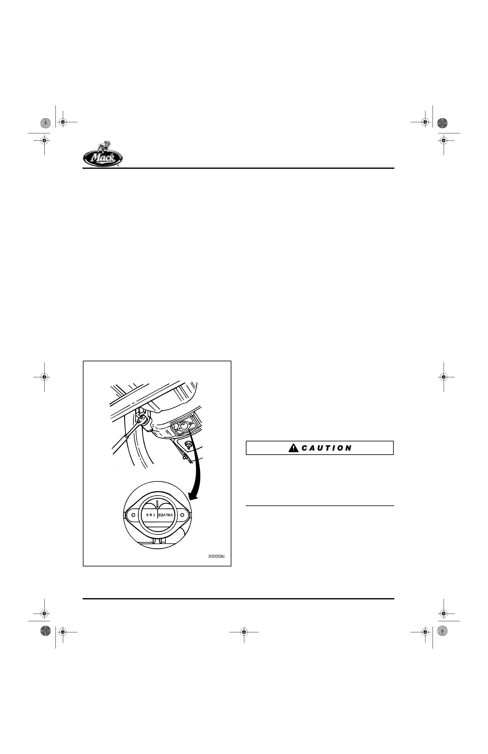
Access to the valve adjustment markings on the
flywheel is achieved by removing the cover from
the bottom of the flywheel housing. Tool
No. J 38587, which engages the flywheel through
an access hole in the flywheel housing, is
recommended to rotate the engine.
540
Figure 540 — Flywheel Valve Adjustment Markings
Valve adjustments are made in two stages. The
exhaust valve yoke is adjusted first, and then the
valve lash. Rotate the engine in the direction of
normal rotation until the valve adjustment
marking is aligned in the center of the access
window.
SPECIAL TOOLS REQUIRED
앫 Engine Barring Socket J 38587-A
앫 Torque Wrench J 24407
앫 T-Handle Torque Screwdriver J 29919
(Torque value preset to 6 lb-in)
앫 Hex Internal Bit, 5 mm
앫 Crow’s Foot Wrench, 8 mm 3/8-Inch Drive
앫 Crow’s Foot Wrench, 13 mm 3/8-Inch Drive
앫 Crow’s Foot Wrench, 14 mm 3/8-Inch Drive
앫 Adapter, 3/8-Inch to 1/4-Inch
앫 Drive Extension, 1/4-Inch
VALVE YOKE AND VALVE LASH
ADJUSTMENT FOR NON-BRAKE ENGINES
Valve Yoke Adjustment Procedure (Non-Brake
Engines)
Adjust the valve yokes at the exhaust valve
positions using the following procedure. As these
engines are equipped with the self-leveling
pinless valve yokes at the inlet positions, only the
exhaust valve yokes need to be adjusted.
Make sure that adjusting screws are retracted
upward in the rocker arms. If the adjusting screws
are not retracted and extend too far below the
rocker arm, the push rods can be bent and valve
lifter rollers damaged or broken when tightening
the rocker arm assembly brackets.
1. Using engine barring socket J 38587-A, or
equivalent, manually rotate engine in normal
rotation direction until pointer in flywheel
housing aligns with the valves 1 and 6 marks
on the flywheel and the No. 1 piston is at top
dead center on the compression stroke.
5-111.bk Page 444 Monday, July 10, 2006 2:26 PM