REPAIR INSTRUCTIONS, PART 3
Page 445
Valve lash must be set using the valve
adjustment marks on the engine flywheel, which
are at 30 degrees ATC. This ensures that the
lifter is on the camshaft base circle and not on the
brake ramp portion of the lobe.
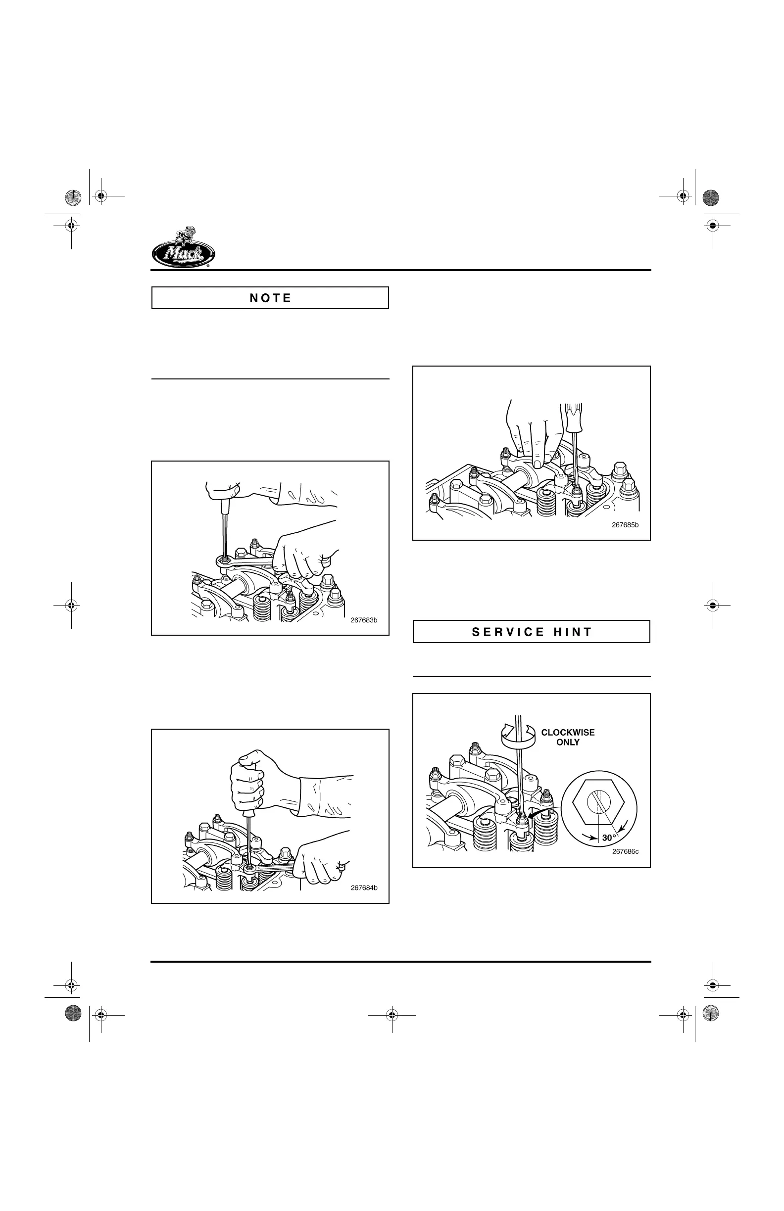
2. Loosen the rocker arm adjusting screw jam
nuts and back out the adjusting screws
several turns. ASET™ engine rocker arm
adjusting screws have a 5 mm internal hex
at the screw head.
541
Figure 541 — Loosening Exhaust Rocker Arm Locknut
and Backing Out Adjusting Screw
3. Loosen the No. 1 cylinder yoke adjusting
screw jam nuts for the exhaust valves. Yoke
adjusting screws for non-brake engines
have a screwdriver slot at the top.
542
Figure 542 — Loosening Exhaust Valve Yoke Adjusting
Screw Locknut
4. Exert moderate force on the valve yoke by
pressing on the rocker arm slipper end. Turn
the yoke adjusting screw clockwise until it
makes solid contact with the outboard valve
stem tip (a light drag should be felt on the
adjusting screw).
543
Figure 543 — Turning Yoke Adjusting Screw Until It
Contacts Valve Stem
5. After the adjusting screw makes solid
contact with the valve stem, turn the screw
clockwise an additional 30 degrees.
A 30-degree turn is equal to 1/2 of a flat on the
adjusting screw jam nut.
544
Figure 544 — Turning Adjusting Screw an Additional
30 Degrees
5-111.bk Page 445 Monday, July 10, 2006 2:26 PM