Page 446
REPAIR INSTRUCTIONS, PART 3
6. Hold the valve yoke adjusting screw in this
position and tighten the adjusting screw jam
nut to the specified torque, 33 lb-ft (45 N폷m),
using torque wrench J 24407, or equivalent.
545
Figure 545 — Yoke Adjusting Screw and Jam Nut
(Slotted Screw Shown)
7. Check the valve yoke adjustment as follows:
a. Insert 0.010-inch (0.25 mm) thickness
gauges between the inboard and
outboard valve stem tips and the valve
yoke.
b. Exert moderate force on the yoke by
pressing on the rocker arm slipper end.
An equal “drag” should be felt on both
thickness gauges. If drag is not equal,
readjust the valve yoke.
546
Figure 546 — Checking Yoke Adjustment
Inlet and Exhaust Valve Lash Adjustment
(Non-Brake Engines)
The following procedure was developed for
adjusting exhaust valve lash on engines
equipped with spring-loaded push rods. This
same procedure, however, can be used for
adjusting inlet valve lash, even though the inlet
valves use standard push rods. If the torque
screwdriver is not available, an alternate
procedure that does not require the torque
screwdriver is outlined in the “Inlet and Exhaust
Valve Lash Adjustment for Non-Brake Engines
(Alternate Procedure)” section that follows.
1. Loosen the rocker arm nut and back out the
adjusting screws at the No. 1 cylinder a
couple of turns and thread the new
flange-head jam nuts on the adjusting
screws, leaving them loose so that
adjustments can be made.
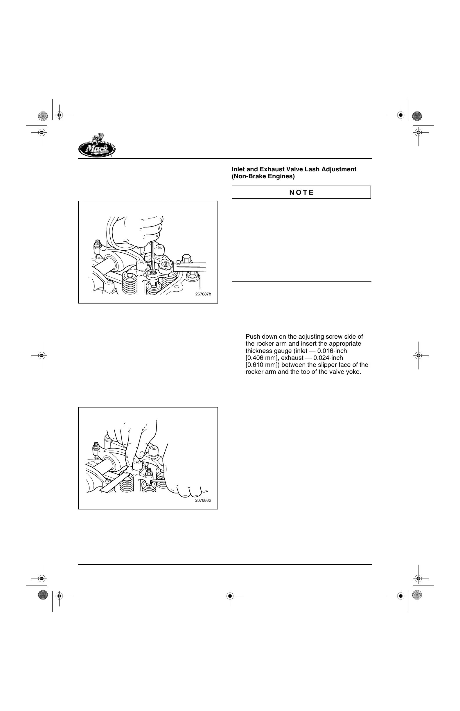
2. Push down on the adjusting screw side of
the rocker arm and insert the appropriate
thickness gauge (inlet — 0.016-inch
[0.406 mm], exhaust — 0.024-inch
[0.610 mm]) between the slipper face of the
rocker arm and the top of the valve yoke.
Leave the thickness gauge in place.
5-111.bk Page 446 Monday, July 10, 2006 2:26 PM