REPAIR INSTRUCTIONS, PART 3
Page 447
547
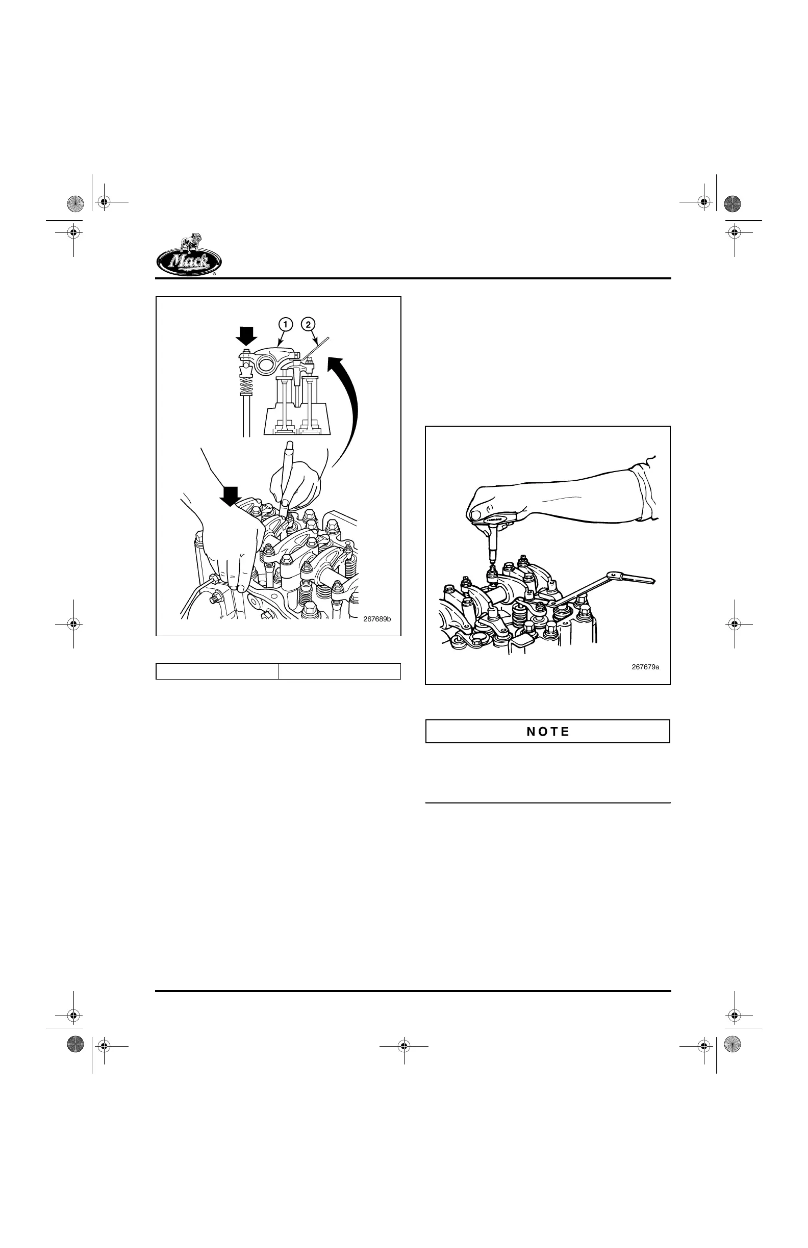
Figure 547 — Inserting Thickness Gauge
3. Using the torque screwdriver, J 29919 or
equivalent, slowly turn the rocker arm
adjusting screw clockwise. At the exhaust
locations, the push rod spring will compress
as the adjusting screw is being tightened. At
the inlet locations, the extra clearance will be
“taken-up” as the adjusting screw is being
tightened.
4. Continue tightening the adjusting screw until
the torque screwdriver clicks. At the exhaust
locations, the push rod spring seats are now
in contact and the push rod is solid and the
valve lash is now properly set. Do not tighten
the adjusting screw any further. At the inlet
locations, when the torque screwdriver
clicks, all excessive lash has been
“taken-up” and inlet lash is now set to the
thickness of the feeler gauge.
548
Figure 548 — Adjusting Exhaust Valve Lash
The torque screwdriver may allow the valve
adjusting screw to loosen slightly when it clicks at
the pre-set torque. Always recheck valve lash
adjustment as described in step 7.
5. Remove the torque screwdriver and hold the
adjusting screw in position with a standard 5
mm Allen wrench to keep it from turning.
Tighten the flange-head jam nut to
specification, 45 lb-ft (61 N폷m).
1. Rocker Arm 2. Feeler Gauge
5-111.bk Page 447 Monday, July 10, 2006 2:26 PM