DESCRIPTION AND OPERATION
Page 33
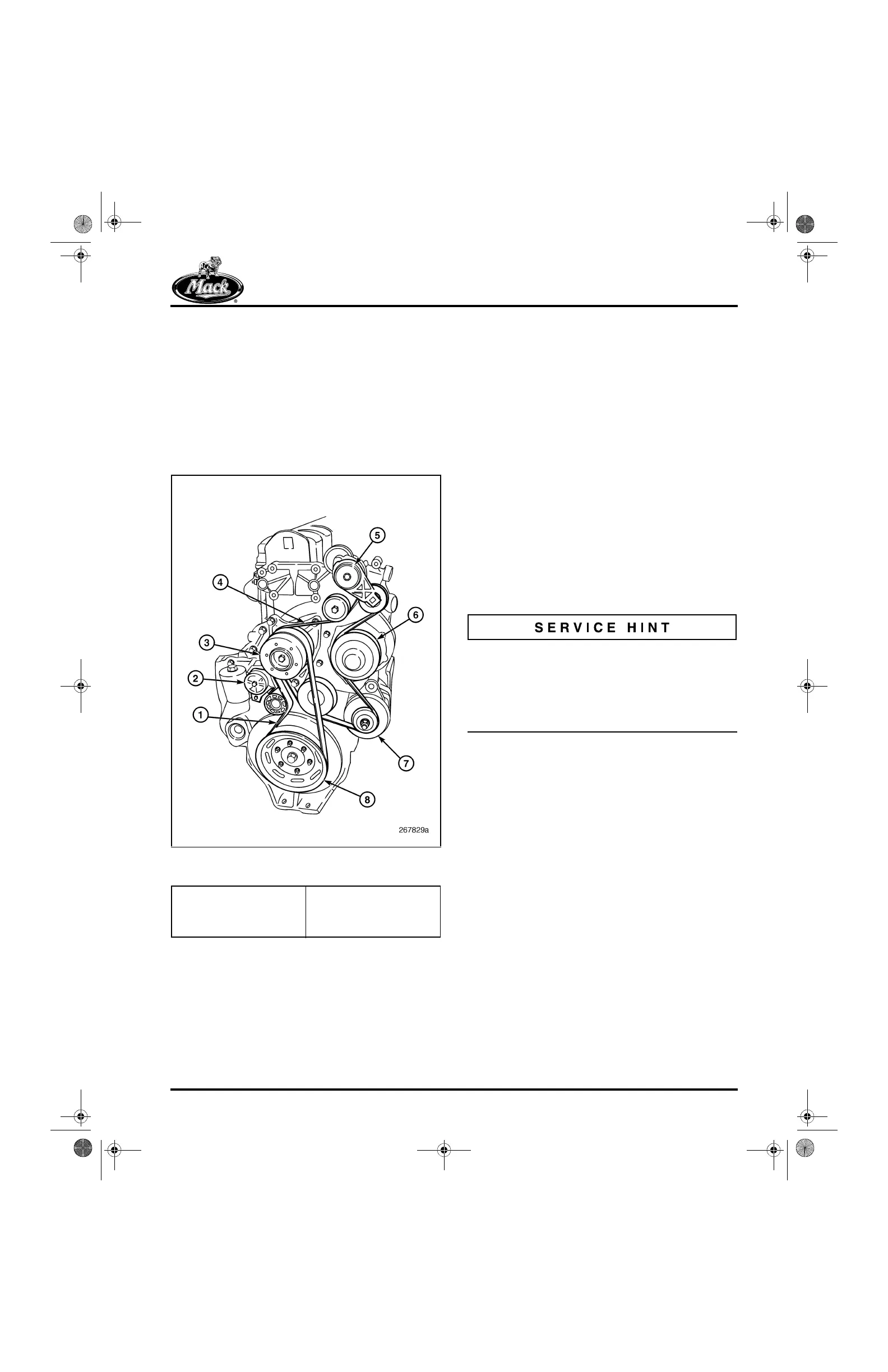
FRONT FAN AND ACCESSORY DRIVE
ARRANGEMENT
In the dual poly-V drive belt arrangement, the fan
drive is driven directly from the crankshaft pulley
by a 10-rib poly-V belt. In turn, the water pump,
alternator and the air conditioning compressor (if
equipped) are driven off the fan-drive hub by a
6-rib poly-V belt (Figure 26). Two tensioners are
used, one for the fan drive and one for the
accessory drive.
26
Figure 26 — Dual Poly-V Drive Belt Arrangement
(Typical Non-AC Application)
Both manually tensioned and automatically
tensioned systems are used. Whether an engine
has the manually tensioned or automatically
tensioned system depends on the specific engine
configuration and application. Service and
adjustment is the same as current engines.
Specific accessory drive belt routing per chassis
is included in the “SCHEMATIC & ROUTING
DIAGRAMS” section of this manual.
VALVE SPRINGS, ROTATORS AND PUSH
RODS
While valve design is unchanged, valve springs
are of a new design. The progressive rate design
is made from an improved material capable of
working under the higher engine speeds. The AC
engine is produced with a single-spring
configuration at the inlet locations and a
dual-spring configuration at the exhaust locations
(Figure 27). The addition of an inner spring at the
exhaust locations assists in seating the valves
under the higher exhaust manifold
back-pressures. The dual-spring configuration
also requires a change in the design of the valve
rotator, the exhaust valve guide and the valve
stem seal.
Current-production exhaust location inner springs
are now being painted white. These springs are
completely interchangeable with the former bare
steel springs. The white paint was added to help
verify that the inner spring is present after the
cylinder head is built-up.
Valve Rotators
The dual-spring exhaust configuration changes
the design of the valve rotator to include seating
surfaces for both the inner and outer valve
springs. This two stepped rotator is shown in
Figure 29.
Early design configurations for both the single
inlet and dual exhaust spring placed the rotators
on the “tip-end” of the valve spring with a
hardened washer at the valve spring seat. The
hardened washers were added to prevent
damage to the cylinder head that could be
caused by the valve spring. Beginning June
2003, the valve spring configuration changed to a
bottom rotator design, however, the single inlet
and dual exhaust spring configuration remained.
The bottom rotator design eliminated the need for
the hardened washer spring seats. With both top
and bottom designs, the rotator used with the
dual springs is different from the rotator used with
the single spring and the correct rotator must be
used.
1. 10-Rib Poly-V Belt
2. Tensioner
3. Fan-Drive Hub
4. 6-Rib Poly-V Belt
5. Tensioner
6. Water Pump
7. Alternator
8. Crankshaft Pulley
5-111.bk Page 33 Monday, July 10, 2006 2:26 PM