REPAIR INSTRUCTIONS, PART 3
Page 449
Inlet and Exhaust Valve Lash Adjustment for
Non-Brake Engines (Alternate Procedure)
If an oz-in or lb-in torque screwdriver or torque
wrench is not available, valve lash can be
adjusted (for both brake and non-brake engines)
in the same manner as described above (by
installing the appropriate thickness gauge and
tightening the adjusting screw), but using careful
hand-pressure to compress the push rod spring
instead of the 6 lb-in torque screwdriver.
Use a 5 mm internal hex wrench in place of the
torque screwdriver to turn the adjusting screw.
Turn the screw clockwise until a large increase in
resistance is felt, indicating that the push rod is
fully compressed and the internal stops of the
push rod upper and lower spring seats are bottom
against each other. No further tightening force is
to be applied to the adjusting screw, or an
inaccurate valve adjustment may result. At that
point, valve lash should be properly set and the
adjusting screw jam nut can be tightened to
45 lb-ft (61 N폷m).
Always recheck the adjustment by exerting
downward pressure by hand on the adjusting
screw and on the rocker arm to fully compress
the push rod while rechecking with the thickness
gauge. When holding the push rod compressed
for the lash overcheck, normal thickness gauge
drag will result. However, after the valve lash is
set, and downward pressure on the rocker arm is
released, the push rod spring pressure will put
increased drag on the thickness gauge.
Continuation of Adjustments for Remaining
Cylinders
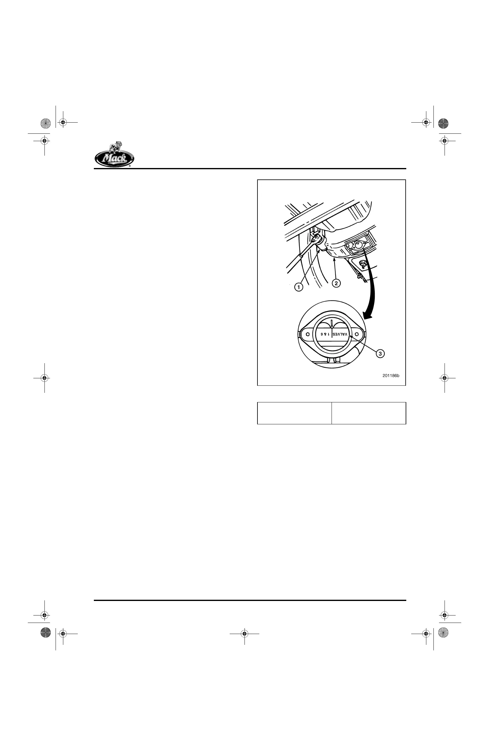
1. Using a barring socket, manually rotate the
engine crankshaft (Figure 551) in normal
rotation direction 120 degrees until the
center of the timing pointer hole in the
flywheel housing aligns with the “2 and 5”
mark on the flywheel and the No. 5 piston is
on the compression stroke.
551
Figure 551 — Valve Adjustment Markings on Flywheel
2. Adjust the final intake and exhaust valve
lash for cylinder No. 5 as described for
cylinder No. 1. Continue this procedure for
each of the remaining cylinders, following
the engine firing order sequence,
1-5-3-6-2-4.
1. Barring Socket
J 38587-A
2. Flywheel Housing
3. Flywheel
5-111.bk Page 449 Monday, July 10, 2006 2:26 PM