REPAIR INSTRUCTIONS, PART 3
Page 451
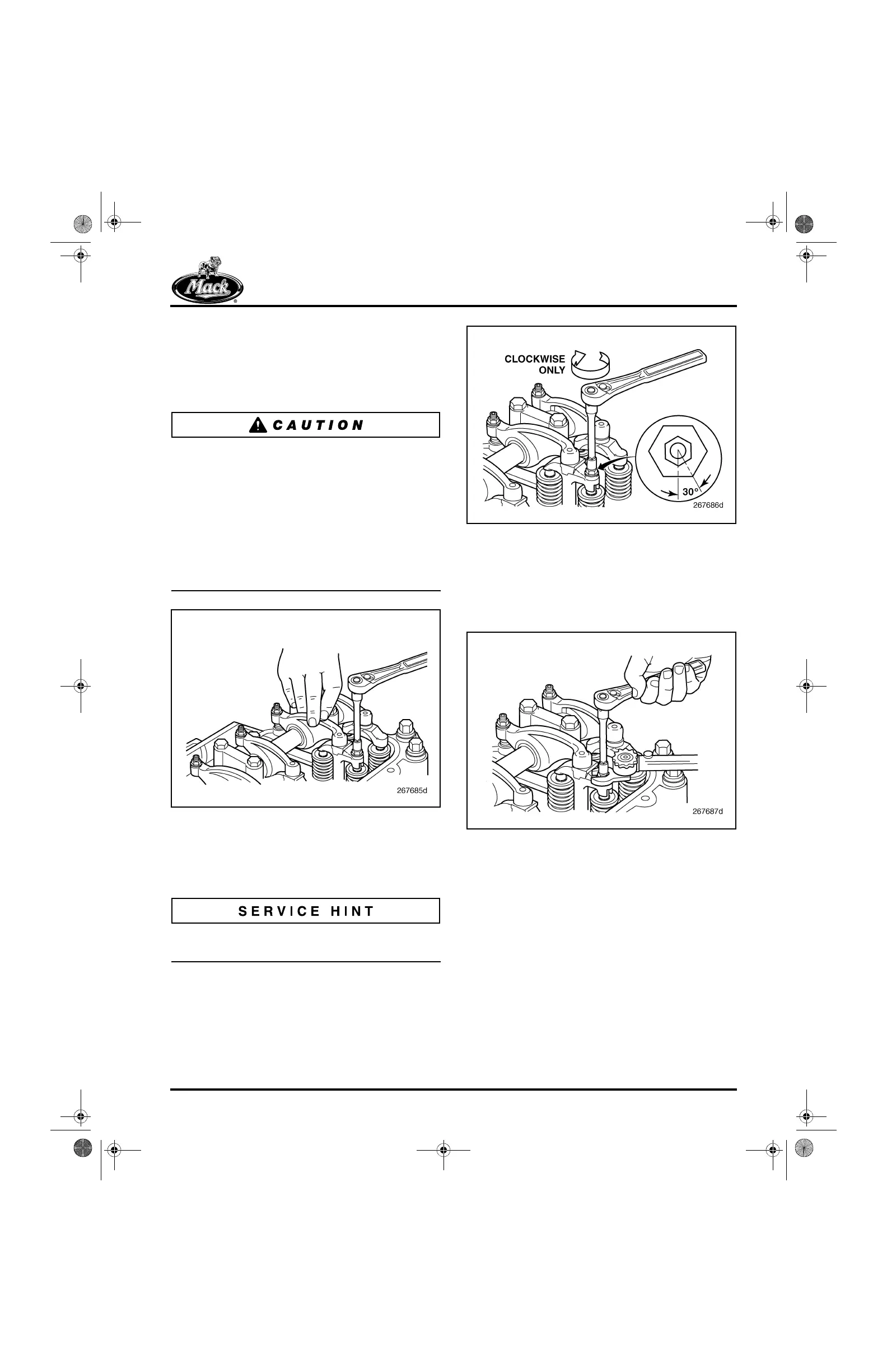
4. Exert moderate force on the valve yoke by
pressing on the rocker arm slipper end. Turn
the yoke adjusting screw clockwise until it
makes solid contact with the outboard valve
stem tip (a light drag should be felt on the
adjusting screw).
Engines equipped with a J-Tech™ engine brake
will have an actuator pin adjusting screw in the
exhaust yoke.
Do not allow anything to press down on the
actuating pin during adjustment. The pin must be
fully extended, approximately 1/4 inch
(6.350 mm) above the top of the hollow adjusting
screw. If the pin is held down and not fully
extended, an improper adjustment and engine
failure will result.
554
Figure 554 — Turning Yoke Adjusting Screw Until It
Contacts Valve Stem
5. After the adjusting screw makes solid
contact with the valve stem, turn the screw
clockwise an additional 30 degrees.
A 30-degree turn is equal to 1/2 of a flat on the
adjusting screw jam nut.
555
Figure 555 — Turning Adjusting Screw an Additional
30-Degree Turn
6. Hold the valve yoke adjusting screw in this
position and tighten the adjusting screw jam
nut to the specified torque, 33 lb-ft (45 N폷m),
using torque wrench J 24407, or equivalent.
556
Figure 556 — Yoke Adjusting Screw and Jam Nut
7. Check the valve yoke adjustment as follows:
a. Insert 0.010-inch (0.25 mm) thickness
gauges between the inboard and
outboard valve stem tips and the valve
yoke.
b. Exert moderate force on the yoke by
pressing on the rocker arm slipper end.
An equal “drag” should be felt on both
thickness gauges. If drag is not equal,
readjust the valve yoke.
5-111.bk Page 451 Monday, July 10, 2006 2:26 PM