Page 458
REPAIR INSTRUCTIONS, PART 3
앫 The torque screwdriver may allow the
adjusting screw to loosen slightly when it
“clicks” at the pre-set torque. It is important
to develop a “feel” for when the screwdriver
click occurs and feel for the actual setting of
the lash. To develop a feel for when the
screwdriver will click, slowly turn the
screwdriver through the function once or
twice, and for the third time, bring the
screwdriver just to the point before it clicks.
Also, at no time should the screwdriver be
turned clockwise after the click has
occurred. Always recheck the adjustment.
앫 When tightening the adjusting screw, it is
important to make sure that the adjusting
screw jam nut is NOT bottomed against the
rocker arm, and that the swivel-head
adjusting screw at the nose end of the
rocker arm is NOT in contact with the valve
yoke.
앫 If either the push rod spring or the brake
actuator plunger are not compressed, brake
lash is not set correctly and the adjustment
procedure must be repeated.
571
Figure 571 — Adjusting Engine Brake Hydraulic
Actuator Lash
5. Remove the T-handle torque screwdriver,
then use a hex-bit screwdriver to hold the
adjusting screw in position. Use an
accurately calibrated torque wrench to
tighten the jam nut to 45 lb-ft (61 N폷m).
572
Figure 572 — Tightening Adjusting Screw Jam Nut
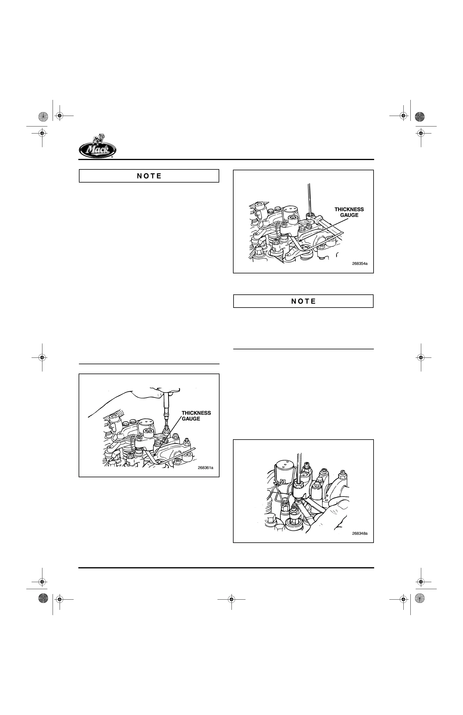
After completing the brake plunger lash
adjustment, leave the 0.045-inch (1.14 mm)
thickness gauge in place. This keeps the plunger
and push rod spring compressed so that the
exhaust valve lash can be adjusted.
Exhaust Valve Lash Adjustment
(PowerLeash™ Brake Engine)
1. With the 0.045-inch (1.14 mm) thickness
gauge in place between the valve yoke and
the hydraulic actuator plunger, insert a
0.024-inch (0.610 mm) thickness gauge
between the adjusting screw “foot” and the
valve yoke. Using a 5 mm Allen wrench, turn
the adjusting screw until a light “drag” is felt
on the thickness gauge.
573
Figure 573 — Adjusting Exhaust Valve Lash
5-111.bk Page 458 Monday, July 10, 2006 2:26 PM
 Loading...

