REPAIR INSTRUCTIONS, PART 3
Page 459
2. Holding the adjusting screw in position, use
an accurately calibrated torque wrench to
tighten the jam nut to 45 lb-ft (61 N폷m).
574
Figure 574 — Tightening Swivel-Head Adjusting Screw
Jam Nut
3. Remove the thickness gauges from between
the swivel-head adjusting screw and valve
yoke, and from between the brake lash
adjuster plunger and the actuating pin.
4. Recheck the exhaust valve lash adjustment
by pressing down on the push rod end of the
rocker arm and inserting the 0.024-inch
(0.610 mm) thickness gauge between the
swivel-head adjusting screw and the valve
yoke. If the adjustment is not correct, both
engine brake and exhaust valve lash must
be re-checked and readjusted as required.
Inlet Valve Adjustment (PowerLeash™ Brake
Engines)
Inlet valve lash is adjusted in the same manner
as non-brake engines.
Continuation of Adjustments for Remaining
Cylinders
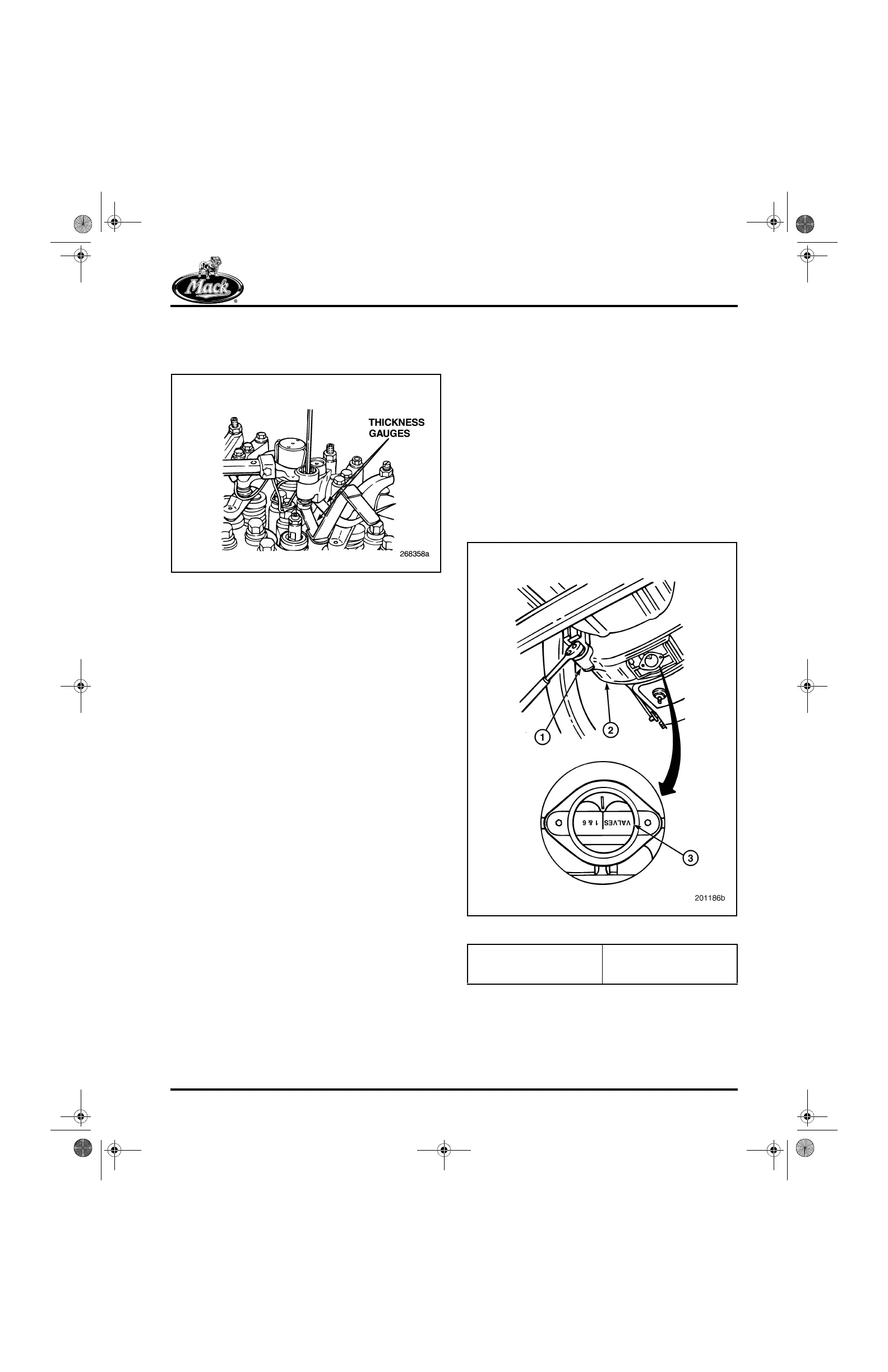
1. Using a barring socket, manually rotate the
engine crankshaft (Figure 575) in normal
rotation direction 120 degrees until the
center of the timing pointer hole in the
flywheel housing aligns with the “2 and 5”
mark on the flywheel and the No. 5 piston is
on the compression stroke.
575
Figure 575 — Valve Adjustment Markings on Flywheel
1. Barring Socket
J 38587-A
2. Flywheel Housing
3. Flywheel
5-111.bk Page 459 Monday, July 10, 2006 2:26 PM
 Loading...

