SPECIFICATIONS
Page 473
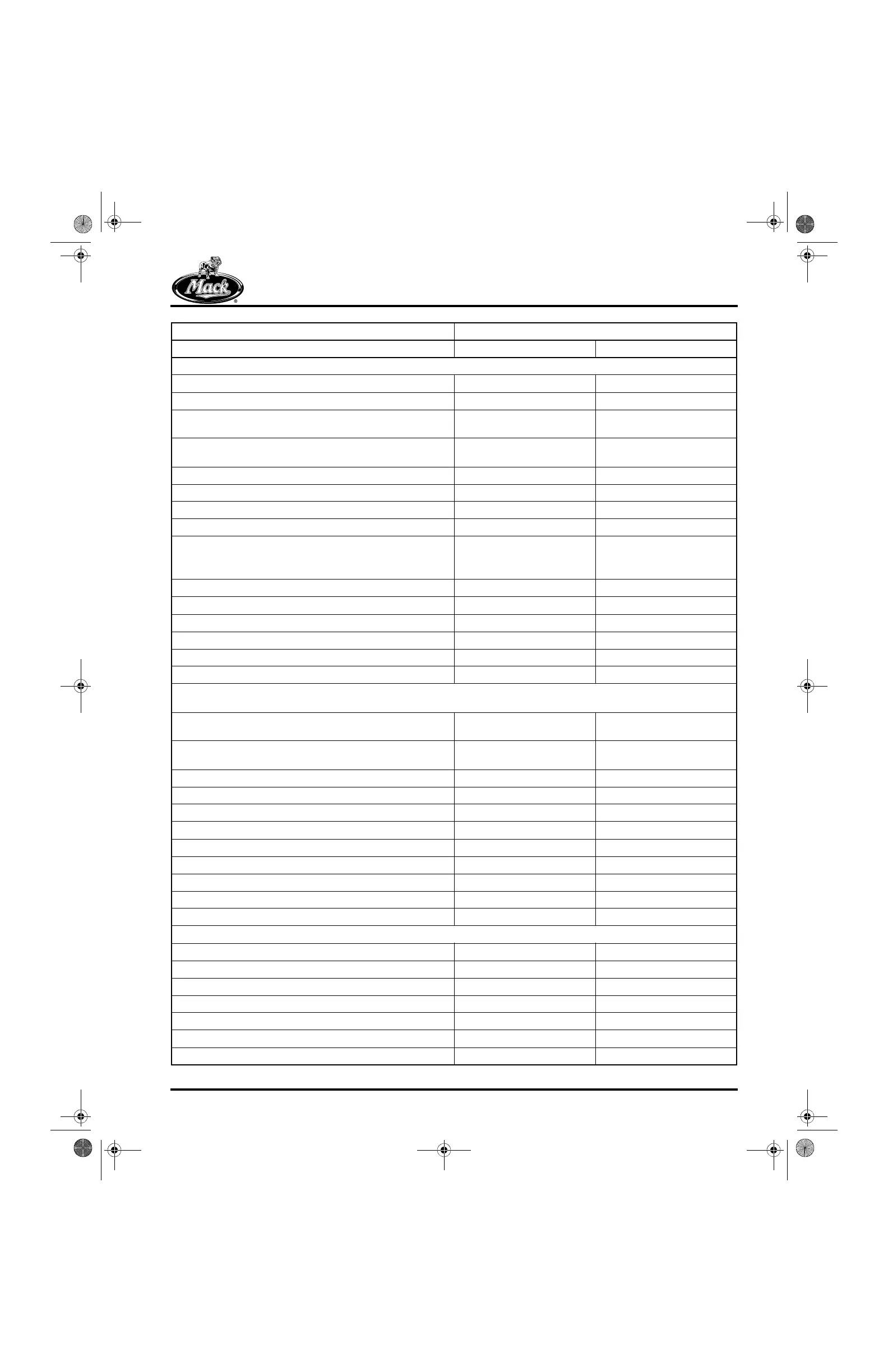
CYLINDER BLOCK
Deck Flatness (across one cylinder head) 0.002 in. 0.0508 mm
Deck Flatness (across both cylinder heads) 0.004 in. 0.1016 mm
Dowel Pin Holes (flywheel housing-to-block mounting, left
side)
0.6237–0.6247 in. 15.8420–15.8674 mm
Dowel Pin Holes (flywheel housing-to-block mounting, right
side)
0.6807–0.6817 in. 17.2898–17.3152 mm
Dowel Pin Holes (front cover-to-block mounting, left side) 0.5557–0.5567 in. 14.1148–14.1402 mm
Dowel Pin Holes (front cover-to-block mounting, right side) 0.4987–0.4997 in. 12.6670–12.6924 mm
Cylinder Bore in Block (upper) 5.501–5.500 in. 139.725–139.970 mm
Cylinder Bore in Block (lower) 5.1266–5.1250 in. 130.2156–130.1750 mm
Cylinder Bore Out-of-Round or Taper (on diameter)
(During manufacturing, the cylinder bores are honed with a
torque-plate [simulated cylinder head] installed.)
0.004 in. max., without torque
plate installed
0.1016 mm
Sleeve OD (at upper pilot diameter) 5.5040–5.5030 in. 139.8016–139.7762 mm
Sleeve Bead for Fire Ring (protrusion above sleeve channel) 0.0067–0.010 in. 0.1702–0.2540 mm
Sleeve in Bore (upper press-fit) 0.004–0.002 in. 0.1016–0.0508 mm
Sleeve in Bore (lower loose fit) 0.0029–0.0003 in. 0.0737–0.0076 mm
Main Bearing Bore in Block 4.818–4.817 in. 122.3772–122.3518 mm
Main Bearing ID (in place) 4.502–4.4996 in. 104.3508–114.2898 mm
Note: Extension of the cylinder sleeve above the cylinder block deck can vary under the same head, as long as all are within
the 0.024–0.029 inch (0.610–0.737 mm) specification for ASET™ AC engines.
Cyl. Sleeve Flange Channel-to-Block Deck (DO NOT
measure from top of bead.)
0.024–0.029 in. 0.610–0.737 mm
Cyl. Sleeve ID (installed, See “NOTE 8 — CYLINDER
SLEEVE ID” on page 489.)
4.876–4.877 in. 123.850–123.876 mm
EUP Tappet Bore 1.7334 + 0.0012/−0.0004 in. 44.028 + 0.0305/−0.0102 mm
EUP Tappet OD 1.7299–1.7307 in. 43.939–43.960 mm
EUP Tappet-to-Bore Clearance 0.0023–0.0047 in. 0.058–0.119 mm
Valve Roller Follower Bore 1.1245–1.1255 in. 28.562–28.588 mm
Valve Roller Follower OD 1.122–1.123 in. 28.499–28.524 mm
Valve Roller Follower-to-Bore Clearance 0.0015–0.0035 in. 0.038–0.089 mm
Valve Roller Follower H-Ring Bore 1.1245–1.1255 in. 28.562–28.588 mm
Valve Roller Follower H-Ring OD 1.1261–1.1265 in. 28.603–28.613 mm
Valve Roller Follower H-Ring-to-Bore Press Fit 0.0006–0.0020 in. 0.015–0.051 mm
CYLINDER HEAD
Alignment Across Exhaust Ports 0.005 in. 0.127 mm
Deck Flatness (over 18 in./45.72 cm) 0.0015 in. 0.0381 mm
Overall Height 6.391–6.397 in. 162.331–162.484 mm
Fire Ring Groove (width) 0.030–0.036 in. 0.762–0.914 mm
Fire Ring Groove (depth) 0.005–0.013 in. 0.127–0.330 mm
Fire Ring Groove ID 5.137–5.139 in. 130.479–130.531 mm
Valve Guide OD 0.6886–0.6881 in. 17.4904–17.4777 mm
Tolerances Are Shown Low to High Standard Size or Fit
Component English Metric
5-111.bk Page 473 Monday, July 10, 2006 2:26 PM