Page 474
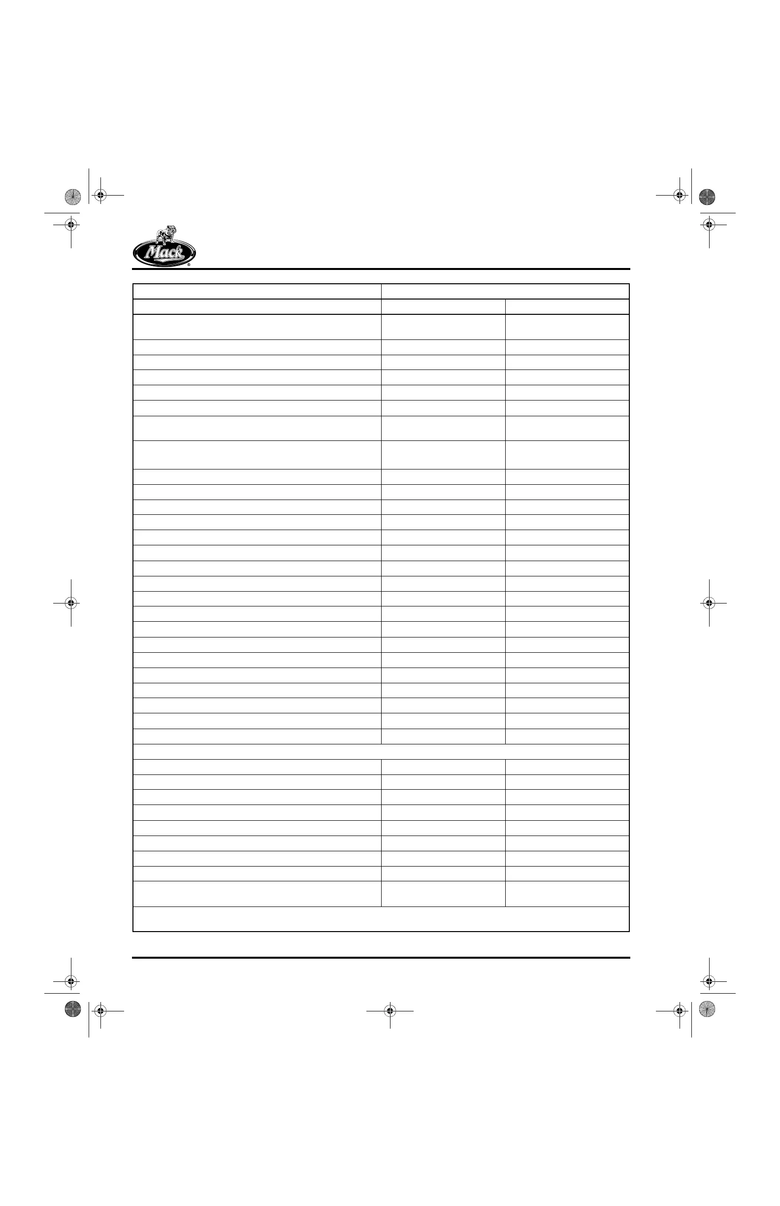
SPECIFICATIONS
Valve Guide Ream ID (after installation, inlet and exhaust,
used with 3/8 valve stem)
0.3745–0.3755 in. 9.5123–9.5377 mm
Top End of Valve Guide-to-Valve Spring Seat 0.857–0.937 in. 21.768–23.710 mm
Valve Guide Bore in Head 0.686–0.687 in. 17.424–17.450 mm
Valve Guide-to-Bore (press-fit) 0.0011–0.0026 in. 0.0279–0.0660 mm
Valve Guide Extension (fire deck to top of guide) 5.178 ± 0.030 in. 131.521 ± 0.762 mm
Yoke Guide Pin OD 0.4389–0.4392 in. 11.1481–11.1557 mm
Yoke Guide Pin Installed Height (above top surface of guide
pin bore to top of pin)
1.848–1.918 in. 46.939–48.717 mm
Valve Seat Width (Inlet)
(Exhaust)
0.060 ± 0.005 in.
0.069 ± 0.005 in.
1.524 ± 0.127 mm
1.753 ± 0.127 mm
Valve Seat Insert Face Angle (inlet) 20° 30′ ± 15′
Valve Seat Insert Face Angle (exhaust) 30° 15′ ± 15′
Valve Seat-to-Guide Runout 0.002 in. F.I.M. 0.0508 mm
Valve Seat Insert Counterbore Diameter (inlet) 1.8285–1.8295 in. 46.4439–46.4693 mm
Valve Seat Insert Counterbore Diameter (exhaust) 1.6875–1.6885 in. 42.8625–42.8879 mm
Valve Seat OD (inlet) 1.831–1.832 in. 46.507–46.533 mm
Valve Seat OD (exhaust) 1.692–1.693 in. 42.977–43.002 mm
Valve Seat Insert (inlet, press-fit in head) 0.0015–0.0035 in. 0.0381–0.0889 mm
Valve Seat Insert (exhaust, press-fit in head) 0.0035–0.0055 in. 0.0889–0.1397 mm
Valve Seat Counterbore Depth (inlet) 0.360–0.364 in. 9.144–9.246 mm
Valve Seat Counterbore Depth (exhaust) 0.372–0.376 in. 9.449–9.550 mm
Injection Nozzle Holder Insert Bore:
Upper Bore 1.07395–1.07545 in. 27.2784–27.3165 mm
Lower Bore 1.058–1.060 in. 26.873–26.924 mm
Lobing (Max. per 30-degree segment) 0.0004 in. 0.010 mm
Injection Nozzle Holder Insert OD:
Upper Sealing Diameter 1.0773–1.0781 in. 27.363–27.384 mm
Lower Sealing Diameter 1.06145–1.06225 in. 26.961–26.981 mm
FLYWHEEL HOUSING
Dowel Pin Hole, Flywheel Housing (round pin, LH) 0.6259–0.6263 in. 15.8979–15.9080 mm
Dowel Pin Hole, Flywheel Housing (blade pin, RH) 0.6831–0.6835 in. 17.3507–17.3609 mm
Dowel Pin Diameter (round pin, LH) 0.6251–0.6255 in. 15.8775–15.8877 mm
Dowel Pin Diameter (blade pin, RH) 0.6821–0.6825 in. 17.3254–17.3355 mm
Crankshaft Seal Mounting Bore 6.748–6.752 in. 171.3992–171.5008 mm
Starter Motor Mounting Bore 3.625–3.629 in. 92.075–92.117 mm
Transmission Mounting Face Axial Runout 0.008 in. TIR (Max)* 0.203 mm TIR (Max)*
Transmission Pilot Bore Radial Runout 0.010 in. TIR (Max)* 0.254 mm TIR (Max)*
Rear Seal Bore Radial Runout (See “NOTE 9 — REAR SEAL
BORE RADIAL RUNOUT” on page 489.)
0.009 in. TIR (Max)* 0.2329 mm TIR (Max)*
* Note: Must be held relative to main bearing bores. Check runout with an alignment bar installed through the cylinder block
main bearing bores.
Tolerances Are Shown Low to High Standard Size or Fit
Component English Metric
5-111.bk Page 474 Monday, July 10, 2006 2:26 PM