Page 38
DESCRIPTION AND OPERATION
EECU — The EECU is a completely new unit
(Figure 33). Because of its increased capacity
and power, a cooling plate is required to maintain
operating temperatures below the maximum
194°F (90°C). Both the control unit and its
fuel-cooled mounting plate are located on the left
side of the engine at the front of the coolant
manifold. Rubber bushings isolate the EECU and
cooling plate from engine vibration.
There are three sets of terminal connectors. All
terminal pins are gold plated to provide low
contact resistance, reduced fretting and corrosion
for long service life. Circuits are routed through
the three connectors, EJ1 (36 pin), EJ2 (89 pin)
and EJ3 (16 pin), for control of:
앫 Engine fueling
앫 Variable geometry turbocharger
앫 Exhaust gas recirculation
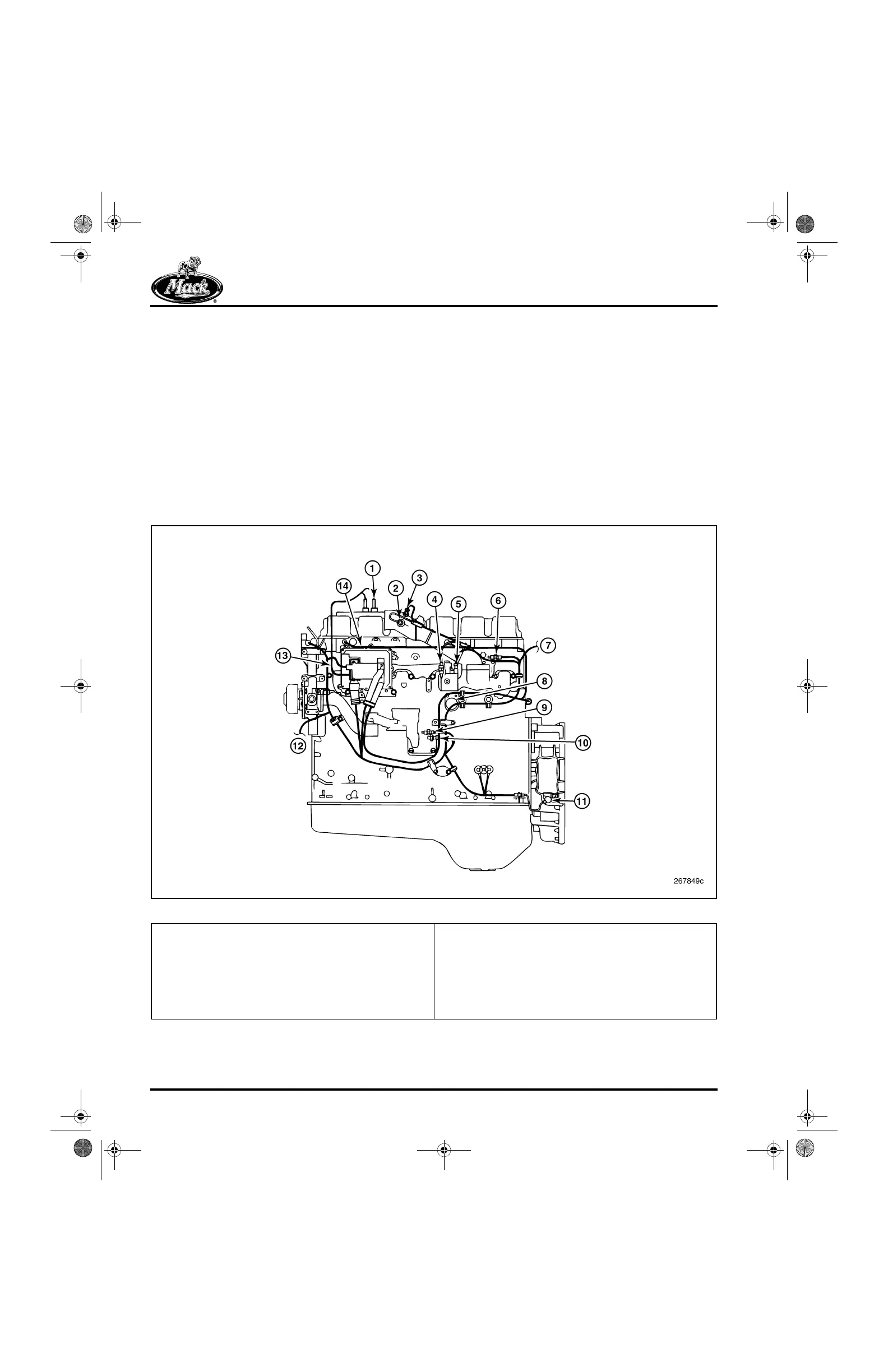
Inputs for the three EECU control loops come
from 16 sensors, six of which are new for the AC
(CEGR) engine. These include chassis-mounted
as well as engine-mounted sensors. Refer to
Figure 34 and Figure 35 for location of the
sensors described below.
34
Figure 34 — ASET™ AC Engine Sensors (Left Side)
1. EGR MASS Flow Sensors
2. Boost Temperature Sensor
3. Boost Pressure Sensor
4. Inlet Manifold Temperature Sensor
5. VTG Control Valve Connector
6. To Chassis-Mounted Combustion Temperature/Humidity
Sensor
7. Coolant Temperature Sensor
8. Deutsch Connector (V-MAC III Engine-to-Chassis
Interface)
9. Oil Temperature Sensor
10. Oil Pressure Sensor
11. Engine Speed Sensor (Speed and Position)
12. To Chassis-Mounted Ambient Air Temperature Sensor
13. Atmospheric Pressure Sensor (Integral to EECU)
14. Engine Brake Harness Leads
5-111.bk Page 38 Monday, July 10, 2006 2:26 PM
 Loading...

