DESCRIPTION AND OPERATION
Page 47
The exhaust rocker arm has two adjusting
screws. The adjusting screw located at the push
rod end of the rocker arm adjusts engine brake
plunger lash. The adjusting screw located at the
valve end of the rocker arm adjusts exhaust valve
lash.
The hydraulic actuator consists of the
following:
— Plunger and spring located in the lower
chamber
— Ball check valve located on top of the
plunger and spring assembly
— Control piston and spring located in the
upper chamber
Solenoid De-Energized — A constant supply of
oil is fed to the actuator to fully lubricate all valve
train components. Spring tension holds the
control piston down to unseat the check valve
ball. With the check valve ball unseated, oil flows
freely into and out of the plunger chambers.
When the engine brake solenoid is not energized,
the plunger assembly can move up and down
freely inside the actuator bore, but spring tension
keeps the plunger seated against the lower snap
ring. This free movement of the plunger provides
the necessary clearance between the bottom
face of the plunger and the exhaust valve
actuating pin during normal engine operation.
45
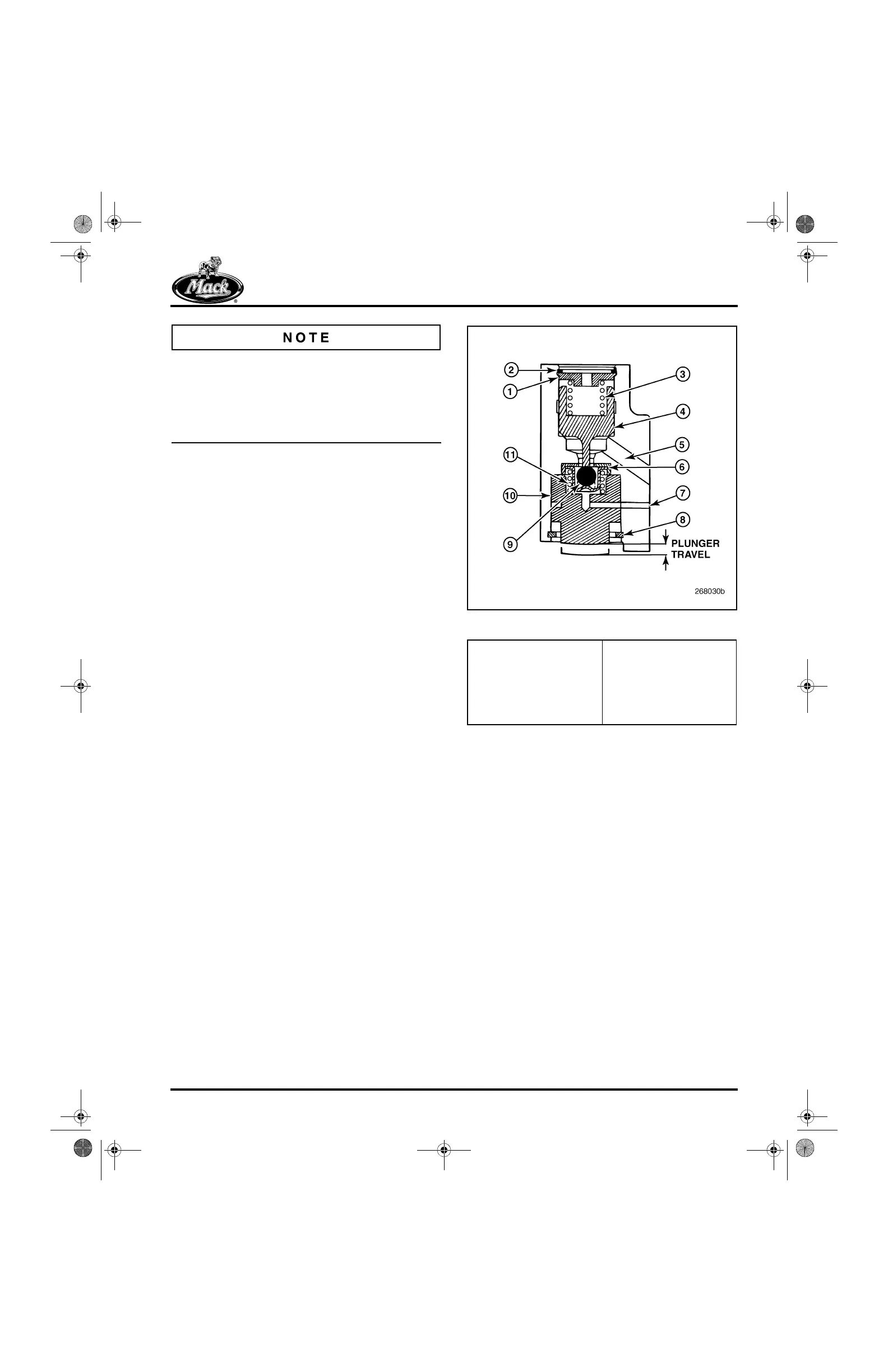
Figure 45 — Hydraulic Actuator Cut-Away View
1. Cover
2. Retaining Ring
3. Control Piston Spring
4. Control Piston
5. Control Oil Port
(Reference Only, Not
Actual Location)
6. Check Valve Assembly
(Check Ball Seat at Top)
7. Leak Down Port
8. Retaining Ring
9. Check Valve Ball
10. Plunger
11. Plunger Spring
5-111.bk Page 47 Monday, July 10, 2006 2:26 PM