Page 48
DESCRIPTION AND OPERATION
Solenoid Energized — When the engine brake
solenoid energizes, oil flows into the rocker shaft
“control” gallery, then from there into the actuator
control piston cavity inside the rocker arm. The
flow of oil moves the control piston upward off its
seat and simultaneously fills the lower plunger
cavity with oil. With the control piston off its seat,
the check valve ball also moves upward. As the
rocker begins to rotate and force the inboard
exhaust valve open, oil pressure in the plunger
cavity increases, forcing the check valve ball to
seat and hydraulically lock the plunger in the
extended position. With the plunger extended,
lash between the plunger and the inboard
exhaust valve is reduced. Continued rotation of
the exhaust valve rocker arm opens the inboard
exhaust valve, thus producing the braking event.
46
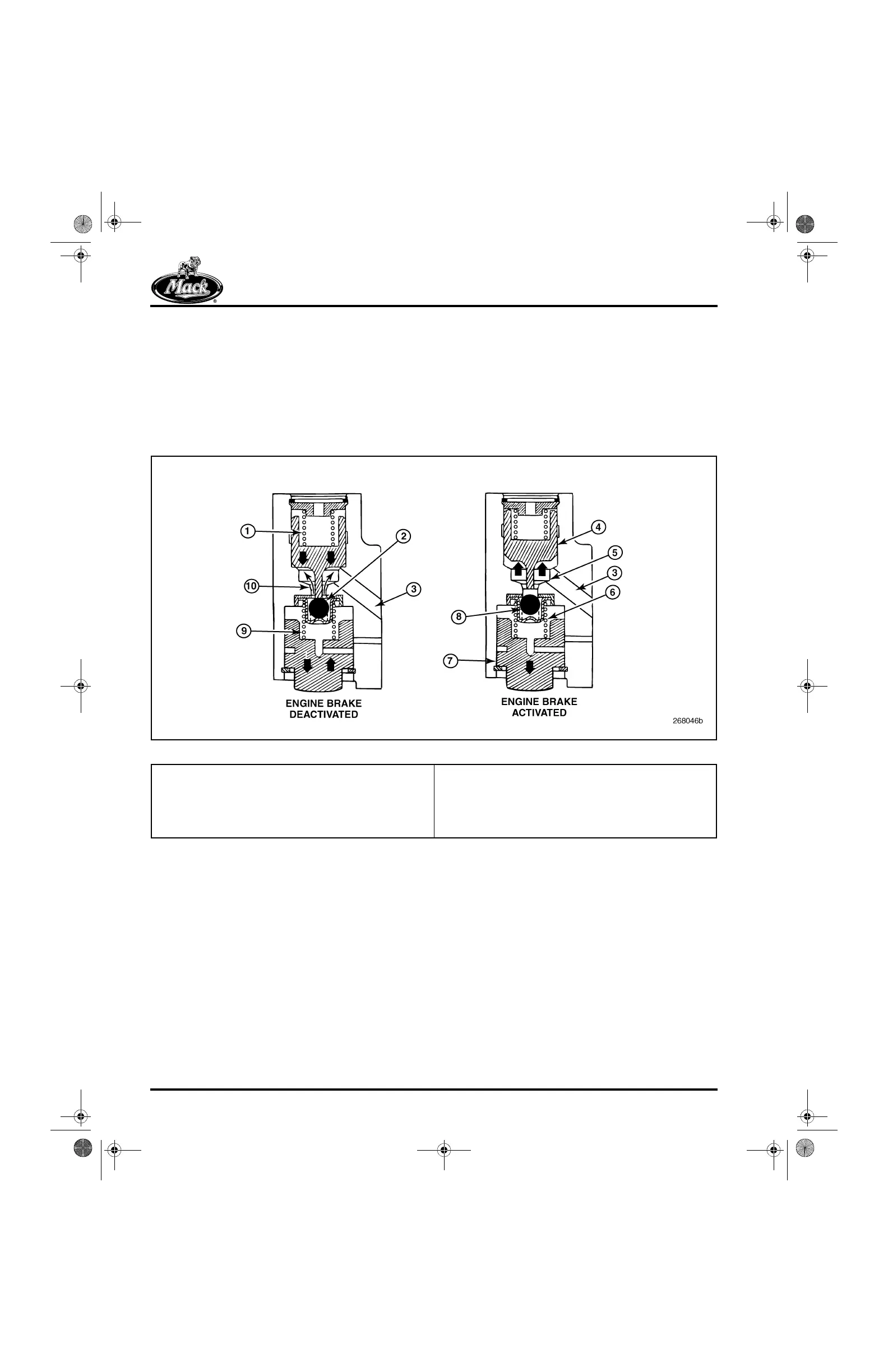
Figure 46 — Hydraulic Actuator Operation
When the engine brake solenoid is de-energized,
the flow of oil to the actuator upper cavity is
removed. Spring tension then pushes the control
piston back down and unseats the check valve
ball. With the check valve ball unseated, oil can
again flow freely in and out of the plunger
chamber, thus removing the hydraulic lock.
Rocker Shaft — The rocker shaft includes two oil
galleries and a port for the solenoid. The upper
gallery supplies “control” oil to the exhaust rocker
arms, and the lower gallery provides a constant
supply of oil to all the rocker arms. When the
engine brake solenoid energizes, oil flows from
the “constant supply” gallery to the “control”
gallery, and in turn, control oil is then supplied to
the hydraulic actuator upper (control piston)
cavity.
1. Spring Tension Holds Control Piston Down
2. Control Piston Unseats Check Valve Ball
3. Control Oil Port (Reference Only, Not Actual Position)
4. Oil Pressure Pushes Control Piston Up Against Spring
Tension
5. Oil Enters Upper Bore
6. Oil Trapped in Plunger Bore
7. Plunger is Hydraulically Locked — Will Not Move Upward
8. Spring Tension Pushes Check Valve Ball
9. Spring Tension Holds Plunger Against Retaining Ring —
Plunger Moves Freely in Bore
10. Oil Flows Freely Past Check Valve Ball
5-111.bk Page 48 Monday, July 10, 2006 2:26 PM