DESCRIPTION AND OPERATION
Page 51
J-TECH™ ENGINE BRAKE FEATURES AND
OPERATION
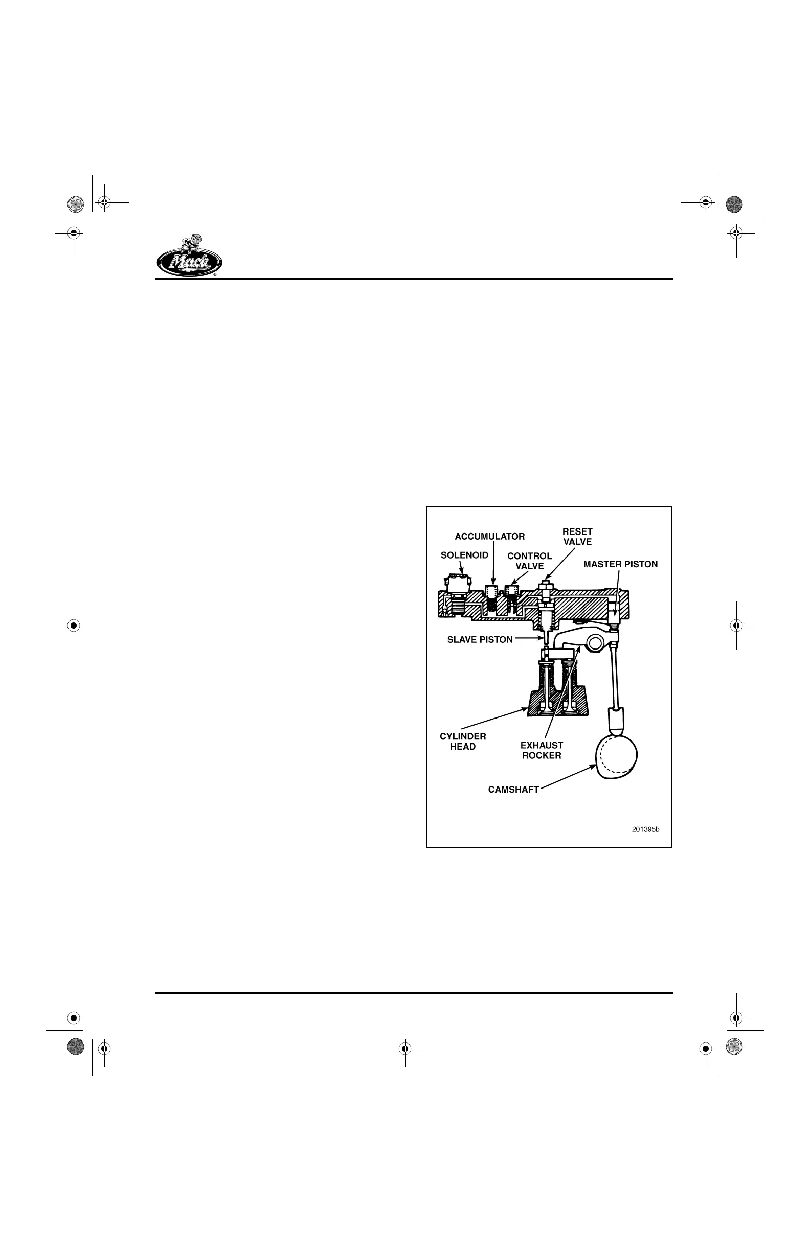
Refer to Figure 52.
The J-Tech™ brake functions in the following
manner:
앫 Under powered operation, a large lash in the
valve train “skips” the 0.100-inch brake
bump on the camshaft.
앫 During engine brake operation, the solenoid
valve is energized, allowing engine oil to fill
the J-Tech™ brake housing oil passages.
앫 Oil overcomes the control valve spring and
drives the control valve up in its bore. Oil
passes through the ball check inside the
control valve and exits through the port in
the side, filling the master/slave piston
circuit.
앫 Oil pressure causes the master piston and
rocker arm to move down, removing the
large lash from the cam side of the valve
train. The result is a corresponding lash
increase on the exhaust valve side.
앫 The brake bump on the exhaust cam forces
the master piston upward and directs
high-pressure oil to the slave piston. The
check valve in the control valve prevents
high-pressure oil from escaping.
앫 High-pressure oil causes the slave piston to
move down, opening the outboard exhaust
valve via a valve-actuating pin that passes
through the center of the yoke adjusting
screw. Activation occurs near top dead
center and releases compressed air into the
exhaust manifold.
앫 At stroke bottom, the slave piston separates
from the reset valve, allowing oil to flow into
the accumulator. This action reduces
pressure in the high-pressure circuit,
permitting the slave piston to retract and the
exhaust valve to close in preparation for
normal exhaust cycle. Oil in the accumulator
ensures the hydraulic circuit is fully charged
for the next cycle.
52
Figure 52 — J-Tech™ Brake
5-111.bk Page 51 Monday, July 10, 2006 2:26 PM