Manitowoc Published 09-09-16, Control # 229-09 10-57
MLC650 SERVICE/MAINTENANCE MANUAL ACCESSORIES
VPC-MAX Trolley Motor Speed Sensor
Speed Sensor Overview
The VPC-MAX trolley is driven by two hydraulic motors.
Each motor contains one speed sensor that is mounted in
the motor case.
The trolley motor speed sensor is a sealed Hall-effect, quad
output, high-current, direction and speed sensing sensor
with a magnetic pickup.
The sensor senses a target ring that is attached to the
rotating cylinder in the motor. The ring’s rotation past the
sensor generates a measurable voltage that is used to
determine the rotational direction and speed of the trolley
motor.
The sensor sends the rotational speed and direction
information to the corresponding control module to be used
by the crane control functions.
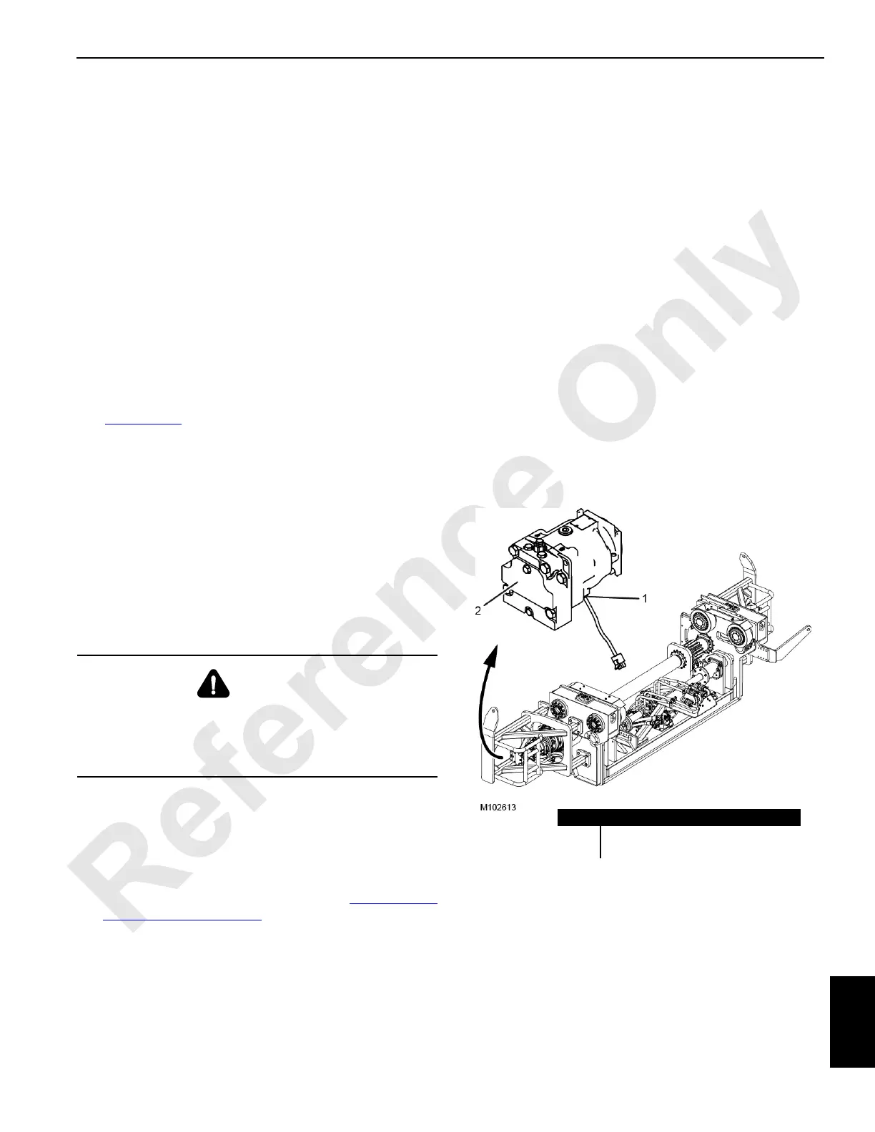
See Figure 10-44
for the following procedures.
Speed Sensor Weekly Periodic Maintenance
• Check that all the speed sensor assembly parts, wiring,
and connections are secure and undamaged.
• Operate the drives to verify that there is a reliable speed
readout on the main display. If there is intermittent or no
readout, troubleshoot the speed sensor assembly.
• Thoroughly clean the sensor of any accumulated dust
and debris.
Speed Sensor Replacement
NOTE: When removing the speed sensor (1) from a motor,
be careful to contain the hydraulic fluid that will
drain from the motor.
1. Loosen the sensor lock nut with an 1-1/16 inch hex
wrench and remove the sensor.
2. Install and adjust the new sensor. See Speed Sensor
Adjustment on page 10-57.
3. Before starting the engine, add clean hydraulic oil of the
correct type to the motor’s top case drain port.
Speed Sensor Adjustment
The speed sensor is set at the factory and should not need
adjustment, unless replaced. When installing or adjusting the
speed sensor on the motor, it must be set at a specific
distance from the target ring on the unit’s rotating cylinder.
Adjust the speed sensor as follows.
1. Loosen the sensor lock nut with an 1-1/16 inch hex
wrench.
2. Turn the sensor clockwise by hand until it contacts the
target ring.
3. Turn the sensor counterclockwise 1/2 turn (180°) to
establish the nominal gap of 0,71 mm (0.028 in).
4. Turn the sensor clockwise until the wrench flats on the
sensor body are positioned at a 22° angle to the pump
shaft centerline.
5. The final sensor position should be between 1/2 turn
(180°) and 1/4 turn (90°) counterclockwise from the point
where the sensor contacts the target ring.
6. Hold the sensor in position with a 1/2 inch hex wrench
while tightening the lock nut to 13 Nm (10 ft-lb).
WARNING
Burn Hazard!
Avoid possible injury. Oil will drain from the port when the
sensor is removed. Wait for the hydraulic oil to cool before
removing the sensor.
Item Description
1 Speed Sensor
2Trolley Motor
FIGURE 10-44