Home
Manitowoc
Construction Equipment
MLC650
Manitowoc MLC650 Service Maintenance Manual
5
of 1
of 1 rating
376 pages
Give review
Manual
Specs
To Next Page
To Next Page
To Previous Page
To Previous Page
Loading...
Reference
Only
Manitowoc
Published 09-09-16, Control # 229-09
2-15
MLC650 SERVICE/MAINTENANCE MANUAL
HYDRAULIC SYSTEM
2
2
Swing Brake, T
ravel
Brake, and Front
Adapter Pin Pusher V
alve Assembly
FIGURE
2-18
Item
Description
1
Swing Brake
2T
r
a
v
e
l
B
r
a
k
e
3
Front Adapter Pin Pul
lers—Extend
4
Front Adapter Pin Pulle
rs—Retract
38
40
Table of Contents
See End of this Manual for Alphabetical Index
5
Table of Contents
5
Section 1
15
Continuous Innovation
15
Safety Messages
15
Safety Alert Symbol
15
Signal Words
15
Safe Maintenance Practices
16
Authorized Repair Personnel Only
16
Basic Crane Maintenance Safety
16
Before Starting a Maintenance Procedure
16
Precautions While Working on the Crane
16
Read this Manual
16
Chemical Handling Precautions
17
Fire Hazard Precautions
17
Maintain Structural Integrity of the Crane
17
Stored Energy Safety Precautions
17
Welding Hazard Avoidance
17
Protection of the Environment
18
Identification and Location of Major Components
18
Returning Crane to Service
18
Solenoid Valve Identification
21
Section 2 Hydraulic System
23
Section 2
23
Hydraulic System Overview
25
Hydraulic Pump Locations
25
Hydraulic Pump Identification
26
Pumps 1, 2, and 4
26
Pump 3
27
Pumps 5, 6, and 8
28
Pump 7
29
Pump 9
29
Hydraulic Motor Identification
30
Variable Displacement Motors
30
Fixed Displacement Motors
33
Manifold Identification
34
Pressure Transducer and Accessories Manifold
34
Upperworks Jacking and Rigging Winch Valve Assembly
35
Mast Assist and Self-Assembly Cylinder Valve Assembly
36
Drum Brakes Release Manifold and Solenoid Valves
37
Pawl Control Manifold
38
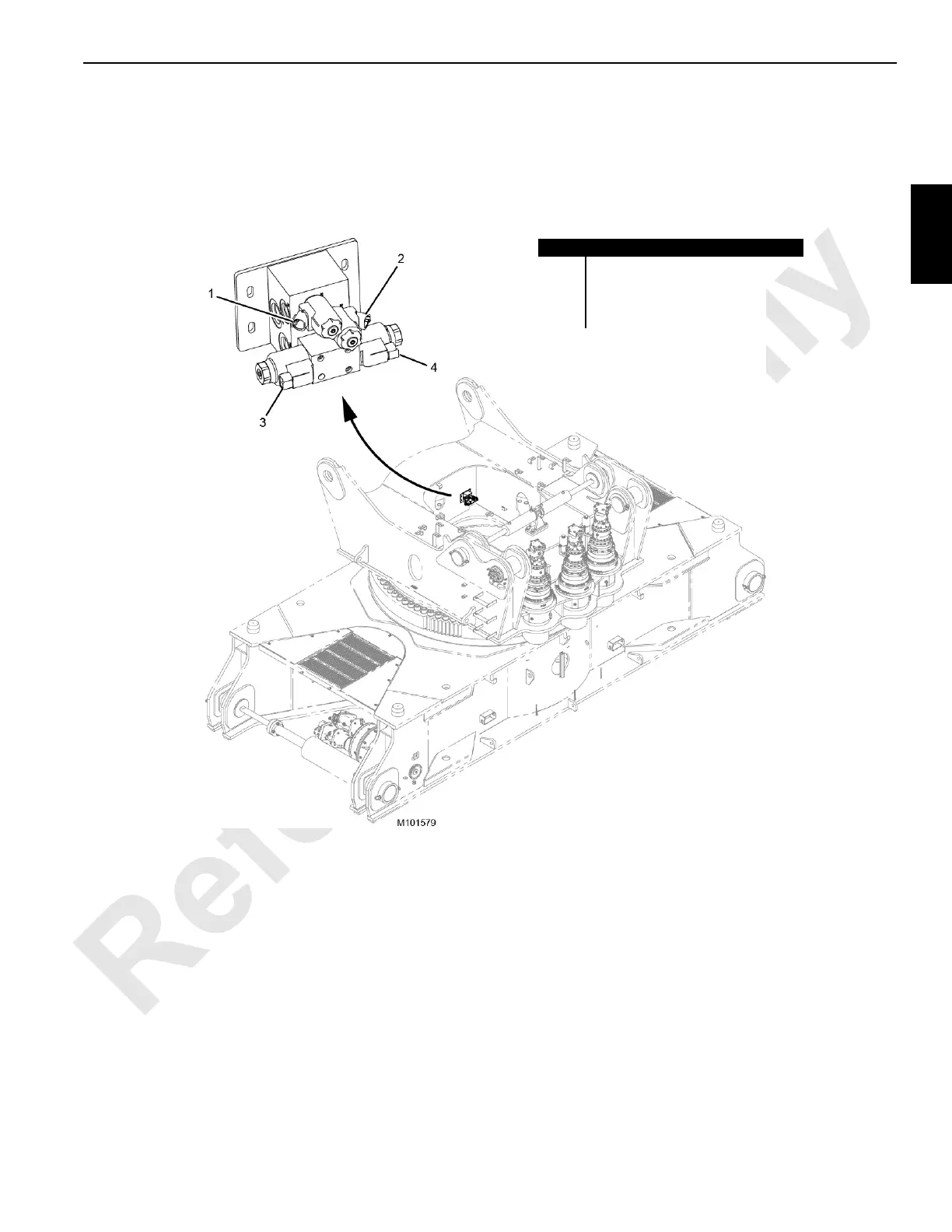
Swing Brake, Travel Brake, and Front Adapter Pin Pusher Valve Assembly
39
Lower Accessories Valve Assembly (Without Jacking Valve)
40
Lower Accessories Valve Assembly (with Jacking Valve)
41
Hydraulic System Specifications
42
Hydraulic System Maintenance
43
Inspecting the Hydraulic System
43
Safety
43
Storing and Handling Oil
43
Storing and Handling Parts
43
Inspecting and Replacing Hydraulic Hoses
44
Replacing the Desiccant Breather Cartridge
46
Replacing the Return Filters
47
Changing the Hydraulic Oil
48
Servicing the Pumps
49
Replacing a Pressure Transducer
50
Shop Procedures
51
Initial Hydraulic Oil Fill
51
Initial Hydraulic System Startup
54
Hydraulic Tests and Calibrations
56
Section 3 Electrical System
61
Section 3
61
Electrical Drawings and Schematics
63
Electrical Power Sequence
63
Battery Power
63
Battery Power Disconnect
63
Crane Electrical Power Distribution
64
Cab Ground Points
65
Crane Electrical System Ground Points
65
Rotating Bed Ground Points
66
Circuit Breakers, Fuses, and Relays
67
Inspect Electrical Components
70
Degradation Due to Severe Environment
70
Every Month or 200 Hours
70
CAN Bus Control System
71
CAN Bus System Overview
71
CAN Bus System Chart
72
Control Module Input/Output (I/O) Types
73
Control Module Naming Conventions
73
Control Modules
73
Crane Control Module (CCM)
73
Safety Control Module (SCM)
73
Input/Output-Large (IOL) Module
77
Input/Output-Small (IOS) Module
78
Control Module Devices
79
Limit Switches-Dual Contact
79
Limit Switches-Single Contact
79
Motor Speed Sensors
79
Pressure Transducers
79
Alarms
80
Angle Sensors
80
Fuel Level Sensor
80
Hydraulic Fluid Level Sensor
80
Load Pin Sensors
80
Solenoids
80
Temperature Sensors
80
Camera Lights
81
Foot Throttle
81
Hand Throttle
81
Pressure and Vacuum Switches
81
Pump Displacement Controls
81
RCL Beacon
81
Relays
81
Travel and Free-Fall Brake Pedals
81
Warning Lights
81
Wind Speed Indicators
81
Control Module Test Voltages
82
Pump and Motor Voltages and Currents
82
Alphabetical Index of Controller Devices
83
Test Voltage Tables
84
Section 4 4 Boom
115
Section 4
115
General Maintenance
117
Boom and Luffing Jib Angle Indicator Calibration
117
Boom Stop Limit Switch
117
Automatic Boom Stop Overview
118
Maintenance
118
Adjusting Automatic Boom Stop
120
Replacing Boom Stop Limit Switch Actuator Rod
120
Physical Boom Stop
121
Physical Boom Stop Operation
121
Boom and Luffing Jib Angle Indicators
122
Mast Angle Sending Unit
122
Adjusting the Mast Angle
122
Fleeting Sheave Maintenance
123
Activation
123
Adjustment
123
General
123
Inspection
123
Operation
123
Replacement
123
Specifications
123
Boom Top Electrical Schematic
124
Luffing Jib Top Electrical Schematic
125
Boom Wind Cap Electrical Schematic
126
Strap Inspection and Maintenance
127
Cranes Not in Regular Use
127
Frequent Inspection
127
Inspection
127
Periodic Inspection
127
Corrosion or Abrasion
128
Identifying Straps
128
Replacement Specifications
128
Flatness
130
Straightness
130
Strap Length
130
Inspection Checklist
131
Removing Straps from Service
131
Storing Straps
131
Lattice Section Inspection and Lacing Replacement
134
Section 5 Hoists
135
Section 5
135
General
139
Drum 1 Main Hoist
139
Drum 1 Brake Operation
139
Drum 1 Brake Overview
139
Drum 1 Hoisting Operation
140
Drum 1 Motor Loop Flushing
140
Drum 1 Lowering Operation
141
Drum 1 Minimum Bail Limit
141
Limit Switch Replacement
141
Weekly Maintenance
142
Drum 1 Hoisting Hydraulic Schematic
144
Drum 1 Lowering Hydraulic Schematic
145
Drum 1 Electrical Schematic
147
Drum 2 Main Hoist
148
Drum 2 Brake Operation
148
Drum 2 Brake Overview
148
Drum 2 Hoisting Operation
149
Drum 2 Motor Loop Flushing
149
Drum 2 Lowering Operation
150
Drum 2 Minimum Bail Limit
151
Limit Switch Replacement
151
Weekly Maintenance
151
Drum 2 Hoisting Hydraulic Schematic
153
Drum 2 Lowering Hydraulic Schematic
154
Drum 2 Electrical Schematic
156
Drum 3 Whip Hoist
157
Drum 3 Brake Operation
157
Drum 3 Brake Overview
157
Drum 3 Motor Loop Flushing
157
Drum 3 Hoisting Operation
158
Drum 3 Lowering Operation
158
Drum 3 Minimum Bail Limit
159
Lowering Limit Switch Replacement
159
Weekly Maintenance
159
Drum 3 Hoisting Hydraulic Schematic
161
Drum 3 Lowering Hydraulic Schematic
162
Drum 3 Electrical Schematic
163
Drum 4 Boom Hoist or Mast Hoist (VPC-MAX™)
164
Drum 4 Brake Operation
164
Drum 4 Brake Overview
164
Drum 4 Motor Loop Flushing
164
Drum 4 Hoisting Operation
165
Drum 4 Lowering Operation
165
Drum 4 Pawl Limit Switch
166
Drum 4 Pawl Operation
166
Limit Switch Replacement
166
Weekly Maintenance
167
Drum 4 Hoisting Hydraulic Schematic
168
Drum 4 Lowering Hydraulic Schematic
169
Drum 4 Electrical Schematic
170
Drum 5 Boom Hoist (VPC-MAX)
171
Drum 5 Brake Operation
171
Drum 5 Brake Overview
171
Drum 5 Hoisting Operation
171
Drum 5 Lowering Operation
172
Drum 5 Pawl Operation
172
Drum 5 Pawl Limit Switch
173
Limit Switch Replacement
173
Weekly Maintenance
173
Drum 5 Hoisting Hydraulic Schematic
175
Drum 5 Lowering Hydraulic Schematic
176
Drum 5 Electrical Schematic
177
Drum 6 Luffing Hoist
178
Drum 6 Brake Operation
178
Drum 6 Brake Overview
178
Drum 6 Motor Loop Flushing
178
Drum 6 Hoisting Operation
179
Drum 6 Lowering Operation
179
Drum 6 Pawl Limit Switch
180
Drum 6 Pawl Operation
180
Limit Switch Replacement
180
Weekly Maintenance
181
Drum 6 Hoisting Hydraulic Schematic
183
Drum 6 Lowering Hydraulic Schematic
184
Drum 6 Electrical Schematic
186
Gearboxes
187
Changing the Gearbox Oil
187
Drum 1 and Drum 2
187
Gear Oil Specifications
187
Monthly or 200 Hours
187
Oil Analysis
187
Periodic Maintenance
187
Quick-Drain Valve
187
Weekly
187
Drum 3
189
Drum 4
189
Drum 5
190
Drum 6
191
Drum Motor Speed Sensor
198
Speed Sensor Replacement
198
Weekly Speed Sensor Periodic Maintenance
198
Block Level
199
Drum 1 and Drum 2
199
Operation
199
Sensor Replacement
199
Block-Up Limit Switch
200
Switch Activation Overview
200
Weekly Maintenance
200
Overview
201
Switch Adjustment and Replacement
201
Main Boom Lower Point Block-Up Limit Switch
203
Main Boom Upper Point Block-Up Limit Switch
205
Main Boom Lower Point 1M Boom Cap Block-Up Limit Switch
206
EUBP Limit 1 Block-Up Limit Switch
207
EUBP Limit 2 Block-Up Limit Switch
208
Luffing Jib Lower Boom Point #682 Top Block-Up Limit Switch
209
Drum 3
210
Overview
210
Pressure Roller
210
Spring Replacement
210
Weekly Maintenance
210
Adjustment
211
Drum 5
211
Spring Replacement
211
Weekly Maintenance
211
Daily Inspection
213
Maintain a Wire Rope Condition Report
213
Required Inspection Intervals
213
Wire Rope Care and Replacement Guidelines
213
Wire Rope Inspection and Replacement
213
Wire Rope Lubrication
213
Determining the Frequency of Inspection
215
Periodic Comprehensive Inspection
215
Reduction in the Rope Diameter
215
Replacement Criteria
215
Broken Rope Wires
216
Distributing Wire Rope Wear
217
Rope that Has Been Idle a Month or more
217
Sheave, Roller, and Drum Inspection
217
Daily Inspection
220
Load Block and Hook-And-Weight Ball Inspection
220
Yearly Inspection
222
Section 6 Swing System
223
General
225
Swing Brake Operation
225
Swing Park Switch Control
225
Momentary Swing Brake Control
225
Swing System Overview
225
Swing Operation
226
Swing Pump Control
226
Swing Left
226
Swing Right
226
Coasting
226
Swing Hydraulic Schematic
227
Swing Electrical Schematic
228
Swing Drive System
229
Planetary Swing Drive
229
Swing Adapter Frame
229
Planetary Swing Drive Gear Oil
230
Gear Oil Specifications
230
Oil Analysis
230
Periodic Maintenance
230
Quick-Drain Valve
230
Changing the Planetary Swing Drive Oil
230
Every 6 Months or 1,000 Hours
230
Monthly or 200 Hours
230
Non-VPC and Non-VPC-Max Planetary Swing Drives
230
Weekly
230
VPC Planetary Swing Drives
231
VPC-MAX Planetary Swing Drives
232
Manual Release of Swing Brake
233
Swing Motor Speed Sensor
234
Speed Sensor Replacement
234
Speed Sensor Adjustment
234
Weekly Periodic Maintenance
234
Section 7 Power Train
235
Section 7
235
Batteries
237
Battery Gases Are Explosive
237
Battery Safety
237
Causes of Battery Failure
237
Jump-Starting a Battery
237
Lack of Water
237
Overcharging
237
Undercharging or Discharged
237
Battery Maintenance
238
Checking Battery State of Charge
238
Loose Hold-Downs
238
Multiple Battery System
238
Overloads
238
Charging
239
Quarterly Battery System Maintenance
239
Troubleshooting-Slow Cranking
239
Storage
240
Battery Disconnect Switch
240
Engine Controls
240
Air Cleaner-Tier 4
241
Daily
241
Inspection
241
Monthly
241
Changing the Filters
242
Air Cleaner-Tier 3
244
Daily
244
Inspection
244
Monthly
244
Changing the Filters
245
Engine Throttle Adjustment
247
Foot Throttle Control
247
Foot Throttle Control Assembly and Calibration
247
Hand Throttle Control
247
Engine Electrical Schematic
249
Tier 4 ECM Electrical Schematic-Power and Ground Circuits
250
Tier 3 ECM Electrical Schematic-Power and Ground Circuits
251
Engine Enclosure
252
Engine Belt Routing
253
Engine Radiator
253
Checking Coolant Level
254
Fill a Drained Cooling System
255
Diesel Particulate Filter
256
Active Regeneration
256
Maintenance
256
Manual Regeneration
256
Passive Regeneration
256
Regeneration
256
Regeneration Inhibit
256
DPF Replacement
257
Installation
257
Removal
257
Section 8 Undercarriage
259
General
261
Hydraulic Travel System
261
Travel System Overview
261
Travel Brake Operation
261
Travel Park Brake Disengage
261
Travel Park Brake Engage
261
Travel Speed Selection
262
Travel Operation
262
High Travel Speed
262
Left Forward Travel Control
262
Low Travel Speed
262
Left Reverse Travel Control
263
Right Forward Travel Control
263
Right Reverse Travel Control
263
Forward Travel (High Speed) Hydraulic Schematic
264
Reverse Travel (Low Speed) Hydraulic Schematic
265
Travel Electrical Schematic
267
Turntable Bearing Alignment
268
Crawler Preventive Maintenance
269
Replacing Turntable Bolts
269
Turntable Bearing Bolt Periodic Tightening
269
Carbody Jack Cylinders and Carbody/Crawler Pin Pullers
270
Carbody Jack Cylinders Control
270
Carbody Manual Control
270
Extend Carbody Jacks Using Manual Control
272
Retract Carbody Jacks Using Manual Control
272
Setup Remote Control
273
Extend Carbody Jacks Using Setup Remote
273
Neutral Position Using Setup Remote
273
Setup Remote Overview
273
Retract Carbody Jacks Using Setup Remote
274
Carbody Jacks Hydraulic Schematic
275
Carbody Jacks Hydraulic Schematic (Remote Control)
276
Carbody Jacks Hydraulic Schematic (Manual Control)
277
Carbody Jacks Electrical Schematic
278
Crawler/Carbody Pin Pullers Control
279
Carbody Manual Control
279
Setup Remote Control
279
Extend Pin Pullers Using Manual Control
279
Retract Pin Pullers Using Manual Control
279
Setup Remote Overview
279
Extend Pin Pullers Using Setup Remote
280
Neutral Position Using Setup Remote
280
Retract Pin Pullers Using Setup Remote
280
Crawler/Carbody Pin Pullers Hydraulic Schematic
281
Crawler/Carbody Pin Pullers Hydraulic Schematic (Remote Control)
282
Crawler/Carbody Pin Pullers Hydraulic Schematic (Manual Control)
283
Crawler/Carbody Pin Pullers Electrical Schematic
284
Crawler Electrical Schematic
285
Crawler Tread Slack Measurement
286
Crawler Tread Slack Adjustment
287
Crawler Tensioning Assembly and Hydraulic Hand Pump
288
Operating the Hand Pump
288
Maintenance
289
Remove Air from the Crawler Tensioning Assembly
289
Lubrication
291
Section 10 Accessories
295
Section 10
295
Adapter Frame-To-Rotating Bed Pin Pullers
299
Adapter Frame-To-Rotating Bed Front Pin Pullers Operation
299
General
299
Setup Remote Overview
299
Extend Pin Pullers Using Setup Remote
300
Neutral Position Using Setup Remote
300
Retract Pin Pullers Using Setup Remote
300
Adapter Frame-To-Rotating Bed Front Pin Pullers Hydraulic Schematic
301
Adapter Frame-To-Rotating Bed Front Pin Pullers Electrical Schematic
302
Adapter Frame-To-Rotating Bed Rear Pin Pullers Operation
303
Extend Pin Pullers Using Setup Remote
303
Neutral Position Using Setup Remote
303
Retract Pin Pullers Using Setup Remote
303
Setup Remote Overview
303
Adapter Frame-To-Rotating Bed Rear Pin Pullers Hydraulic Schematic
304
Adapter Frame-To-Rotating Bed Rear Pin Pullers Electrical Schematic
305
Rotating Bed Jack Cylinders
306
General
306
Neutral Position Using Setup Remote
307
Retract Jack Cylinder Using Setup Remote
307
Setup Remote Control
307
Setup Remote Overview
307
Extend Jack Cylinder Using Manual Control
308
Manual Control
308
Retract Jack Cylinder Using Manual Control
308
Upperworks Jacking and Rigging Winch Valve Assembly
309
Rotating Bed Jacks Hydraulic Schematic
310
Rotating Bed Jacks Hydraulic Schematic (Remote Control)
311
Rotating Bed Jacks Hydraulic Schematic (Manual Control)
312
Rotating Bed Jacks Electrical Schematic
313
Rotating Bed Jack Stowage Cylinder
314
General
314
Extend Stowage Cylinder Using Setup Remote (Stowage Position)
315
Neutral Position Using Setup Remote
315
Retract Stowage Cylinder Using Setup Remote (Working Position)
315
Rotating Bed Jack Stowage Cylinder Operation
315
Setup Remote Overview
315
Rotating Bed Jack Stowage Cylinders Hydraulic Schematic
316
Rotating Bed Jack Stowage Cylinder Electrical Schematic
317
Rigging Winch (Drum 0)
318
General
318
Neutral Position Using Setup Remote or J1 Joystick
318
Setup Remote and J1 Joystick Control
318
Setup Remote Overview
318
Spool in Using Setup Remote or J1 Joystick
318
Spool out Using Setup Remote or J1 Joystick
318
Manual Control
319
Spool in Using Manual Control
319
Spool out Using Manual Control
319
Rigging Winch (Drum 0) Hydraulic Schematic
320
Rigging Winch (Drum 0) Hydraulic Schematic (Remote Control)
321
Rigging Winch (Drum 0) Hydraulic Schematic (Manual Control)
322
Rigging Winch (Drum 0) Electrical Schematic
323
Mast Assist Cylinders
324
General
324
Extend Mast Assist Cylinders Using Setup Remote or Switch
325
Neutral Position Using Setup Remote or Switch
325
Retract Mast Assist Cylinders Using Setup Remote or Switch
325
Setup Remote and Switch Control
325
Setup Remote Overview
325
Mast Assist and Self-Assembly Cylinders Valve Assembly
326
Mast Assist Cylinders Hydraulic Schematic
327
Mast Assist Cylinders Hydraulic Schematic (Setup Remote and Switch Control)
328
Mast Assist Cylinders Electrical Schematic
329
Self-Assembly Cylinder (Optional)
330
General
330
Extend Cylinder Using Setup Remote or J4 Joystick
331
Neutral Position Using Setup Remote or J4 Joystick
331
Retract Cylinder Using Setup Remote or J4 Joystick
331
Setup Remote and J4 Joystick Control
331
Setup Remote Overview
331
Self-Assembly Cylinder Hydraulic Schematic
332
Self-Assembly Cylinder Hydraulic Schematic (Setup Remote and J4 Joystick Control)
333
Self-Assembly Cylinder Electrical Schematic
334
Cab Tilt
335
Cab Tilt down Using the Cab Tilt Switch
335
Cab Tilt in Neutral
335
Cab Tilt up Using the Cab Tilt Switch
335
Cab Tilt Cylinder Hydraulic Schematic (Neutral)
336
Cab Tilt Cylinder Hydraulic Schematic (Tilt up and Tilt Down)
337
Cab Tilt Electrical Schematic
338
VPC and VPC-MAX Systems
339
General
339
Setup Remote Overview
340
VPC Counterweight Tray Operation
340
VPC Counterweight Tray Extension
341
VPC Counterweight Tray Retraction
341
VPC Counterweight Tray Motor Brakes
342
VPC Counterweight Tray Hydraulic Schematic
343
VPC Electrical Schematic
344
Speed Sensor Adjustment
345
Speed Sensor Overview
345
Speed Sensor Replacement
345
Speed Sensor Weekly Periodic Maintenance
345
VPC Counterweight Tray Motor Speed Sensor
345
Absolute Encoder Backlash Adjustment
346
Absolute Encoder Overview
346
VPC Counterweight Tray Absolute Encoder
346
Forward Limit Switch Adjustment
347
Rear Limit Switch Adjustment
347
VPC Counterweight Tray Limit Switches
347
VPC Counterweight Tray Roller Backlash Adjustment
348
Gantry Limit Switch Adjustment
349
Live Mast Limit Switch Adjustment
349
Setup Remote Overview
350
VPC-MAX Trolley Operation
350
Trolley Extension
351
Trolley Retraction
351
Extend Trolley Pin Pullers Using Setup Remote
352
Retract Trolley Pin Pullers Using Setup Remote
352
Trolley Motor Brakes
352
VPC-MAX Trolley Pin Pullers
352
VPC-MAX Trolley Hydraulic Schematic
353
VPC-MAX Trolley Electrical Schematic
354
Speed Sensor Adjustment
355
Speed Sensor Overview
355
Speed Sensor Replacement
355
Speed Sensor Weekly Periodic Maintenance
355
VPC-MAX Trolley Motor Speed Sensor
355
Absolute Encoder Backlash Adjustment
356
Absolute Encoder Overview
356
VPC-MAX Trolley Absolute Encoder
356
VPC-MAX Trolley Roller Backlash Adjustment
357
VPC-MAX Beam Pin Pullers
358
VPC-MAX Frame Assembly Auxiliary Member to VPC-MAX Beam Assembly
359
VPC-MAX Beam Pin Puller Hydraulic Schematic
360
VPC-MAX Beam Electrical Schematic
361
Maximum Tray in Switch Adjustment
362
Maximum Tray out Switch Adjustment
362
VPC-MAX Beam Switch Adjustments
362
Beam up Limit Switch Adjustment
363
VPC-MAX Beam up Limit Switch Adjustment
363
VPC-MAX on Hook Limit Switch Adjustment
364
Active Fixed Mast Stop System
365
General
365
Active Fixed Mast Stop Operation
366
Hydraulic Supply
366
Normal Operation-Cylinder Extension
366
Normal Operation-Cylinder Retraction
367
High Load Operation-Compression
368
High Load Operation-Extension
369
Loss of Load Operation
370
Active Fixed Mast Stop Hydraulic Schematic
371
Active Fixed Mast Stop Electrical Schematic
372
Other manuals for Manitowoc MLC650
Operator's Manual
360 pages
5
Based on 1 rating
Ask a question
Give review
Questions and Answers:
Need help?
Do you have a question about the Manitowoc MLC650 and is the answer not in the manual?
Ask a question
Manitowoc MLC650 Specifications
General
Brand
Manitowoc
Model
MLC650
Category
Construction Equipment
Language
English
Related product manuals
Manitowoc VPC-MAX MLC650
234 pages
Manitowoc MLC300
332 pages
Manitowoc MLC100-1
218 pages
Manitowoc MLC165-1
256 pages
Manitowoc 2250
312 pages
Manitowoc 14000
270 pages
Manitowoc Grove RT890E
24 pages
Manitowoc 14000 2 Series
4 pages
Manitowoc 14000 1 Series
6 pages
Manitowoc 16000 Series 2
2 pages
Manitowoc Grove GMK 5250L
958 pages
Manitowoc Shuttlelift CD5520
144 pages