Manitowoc Published 09-09-16, Control # 229-09 10-49
MLC650 SERVICE/MAINTENANCE MANUAL ACCESSORIES
VPC Counterweight Tray Limit Switches
Forward Limit Switch Adjustment
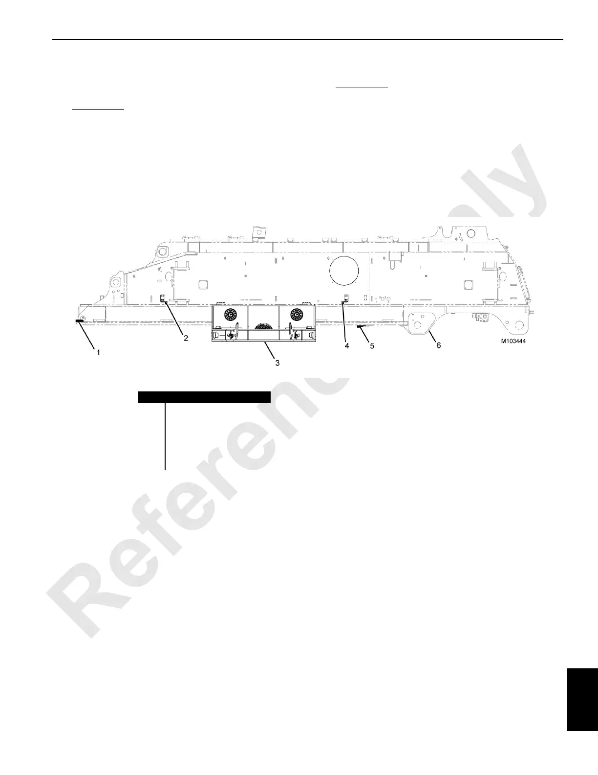
See Figure 10-38 for the following.
The forward limit switch (4) is used to stop the tray before it
reaches the forward physical stop (5).
Adjust the forward limit switch position so that it will trip when
there is 408 mm (16.1 in) between the physical stop on the
VPC counterweight tray (3) and the physical stop on the
rotating bed (6).
Rear Limit Switch Adjustment
See Figure 10-38 for the following.
The rear limit switch (2) is used to stop the VPC
counterweight tray (3) before it reaches the rear physical
stop (1).
With the rear stop installed, adjust the rear limit switch so
that it trips when the counterweight tray is 596 mm (23.5 in)
away from the rear physical stop.
Item Description
1 Rear Physical Stop
2 Rear Limit Switch
3 VPC Counterweight Tray
4Forward Limit Switch
5 Forward Physical Stop
6 Rotating Bed
FIGURE 10-38