Manitowoc Published 09-09-16, Control # 229-09 10-71
MLC650 SERVICE/MAINTENANCE MANUAL ACCESSORIES
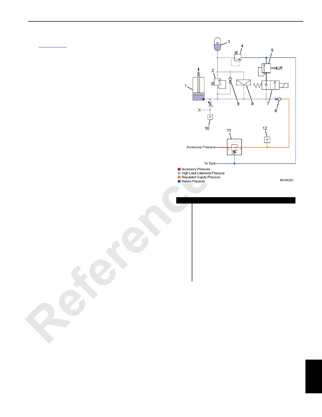
High Load Operation—Extension
See Figure 10-58 for the following.
After a high load event and when the mast stop cylinder
starts to extend, a lower pressure is created in the cylinder
bore versus the stored accumulator pressure. The higher
pressure at the accumulator causes the bypass check valve
(9) to open, allowing the hydraulic fluid stored in the
accumulator to reenter the cylinder bore. Hydraulic fluid from
the system supply circuit also flows to the cylinder bore via
the check valve (6).
Once the system pressure has stabilized, the excess oil in
the accumulator will bleed off through the relief valve (4) and
return to the tank.
Item Description
1 Mast Stop Cylinder
2 Relief Valve (set at 221 bar [3200 psi])
3 Integrated Cylinder Accumulator
4 Relief Valve (set at 16,6 bar [240 psi])
5 Mast Cylinder Pressure-Reducing Solenoid Valve
6 Check Valve
7 Mast Cylinder Directional Control Solenoid Valve
8Rupture Disc
9 Bypass Check Valve
10 Mast Cylinder Pressure Transducer
11 Mast Cylinder System Pressure-Reducing Valve
(set at 31 bar [450 psi])
12 Mast Cylinder System Pressure Transducer
High Load Extension
FIGURE 10-58