HYDRAULIC SYSTEM MLC650 SERVICE/MAINTENANCE MANUAL
2-18
Published 09-09-16, Control # 229-09
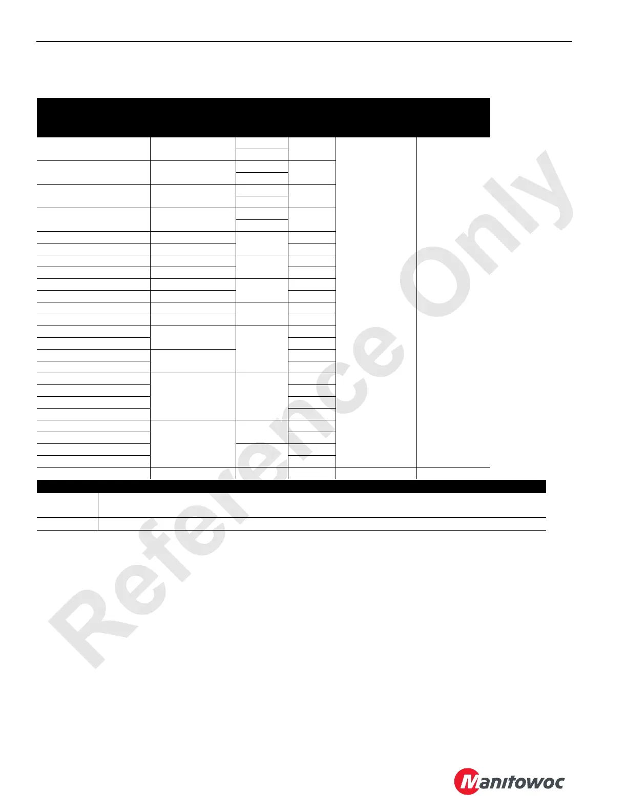
HYDRAULIC SYSTEM SPECIFICATIONS
Table 2-1. Hydraulic Specifications
Function
Speed
1
rpm
Pump
Number
Pump
Port
Pump
Pressure 1
2
bar (psi)
Charge
Pressure
bar (psi)
Drum 1 Hoist Up 39 to 44 1 A
420 (6090) 24 (348)
3
Drum 1 Hoist Down 37 to 41 1 B
3
Drum 2 Hoist Up 39 to 44 2 A
4
Drum 2 Hoist Down 37 to 41 2 B
4
Drum 3 Hoist Up 39 to 44
2
A
Drum 3 Hoist Down 37 to 41 B
Drum 4 Hoist Up 17 to 19
5
A
Drum 4 Hoist Down 16 to 18 B
Drum 5 Hoist Up 25 to 28
6
A
Drum 5 Hoist Down 24 to 26 B
Drum 6 Hoist Up 25 to 28
1
A
Drum 6 Hoist Down 24 to 26 A
Swing Left—Liftcrane
1.3
8
A
Swing Right—Liftcrane B
Swing Left—VPC-MAX
0.87
A
Swing Right—VPC-MAX B
VPC Tray Rearward
N/A 7
A
VPC Tray Forward B
VPC Beam Rearward A
VPC Beam Forward B
Right Travel Reverse
6.3 at tumbler
4
A
Right Travel Forward B
Left Travel Reverse
3
A
Left Travel Forward B
Accessories N/A 9 B 30 (435) N/A
Notes
1
Speeds based on engine at high idle, no load (no rope on drums), and handles moved fully forward or
back. Speeds can very plus or minus 5%.
2 Controlled by multi-function valves in each pump.